4 Z Axis Leadscrews
-
@Snyggis-0 This wasn't possible with the old config tool, but is if you're using the latest one: https://configtool.reprapfirmware.org/Configuration.
There's a '+' icon in the driver column:
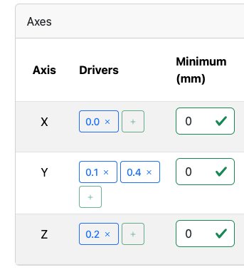
Make sure you have enough drivers defined first.
Ian
TronXY X5S with Duet 3 MB6HC and Roto toolboard : Cartesian bed-slinger with Duet 3 Mini 5+ WiFi and 1LC : RRP Fisher Delta v1 with Duet 2 Maestro : Polargraph with Duet 2 WiFi
-
@Snyggis-0 I see you started a new thread that is really a continuation of this one.
@Snyggis-0 said in Multiple Z stops:
rying to configure my 4 end stops for the z axis(with 4 motors and lead screws). The switches are wired, but when I try to the methods to verify them they dont seem to work with multiple swithches.
Green Box - this doesnt light up
M199 - Doesnt display
Endstop plugin - They extra ones are not displayed
Does anyone know how to get these to show up?Lets continue the discussion here. can you post your config.g to show how they are setup.
-
 undefined T3P3Tony referenced this topic
-
@Snyggis-0 if both Y motors are driving a single Y axis then you don't need to create additional axis. Just assign two drivers to the Y axis in the M584 command. Similarly for 4 motors driving a single Z axis.
Duet WiFi hardware designer and firmware engineer
Please do not ask me for Duet support via PM or email, use the forum
http://www.escher3d.com, https://miscsolutions.wordpress.com -
I am attaching my config file. I was able to assign all of the axis with their appropriate end stops. At this point I am trying to test the switches before I run the homing routine.
Because I have 4 on the z axis, I dont see how to check them individually. I tried all the steps in the commissioning guide, but cant see how it would apply to multiple switches on one axis? I can trigger the X just fine and see it working, but the other ones dont seem to be working.
Please let me know if I need to attach the whole config file.
Thanks!
Scott
-
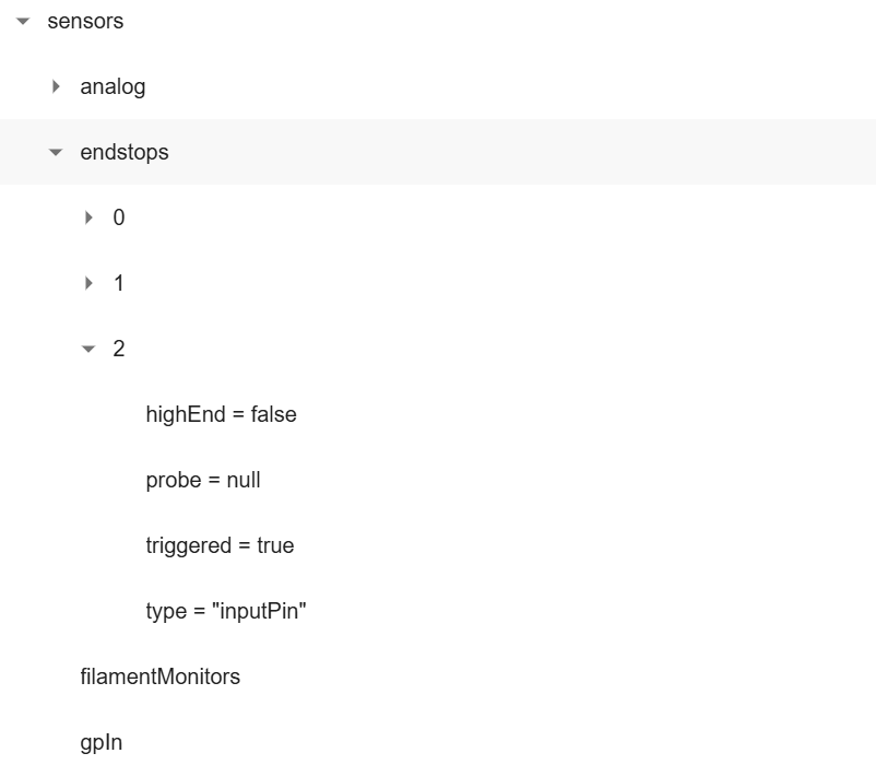
@Snyggis-0 to check that all the endstops are working, enable the Object Model browser plugin in Duet Web Control, then go to the Object Model browser tab and expand
sensorsand thenendstops. Pressing any one of the four Z endstop switches should change the displayed status to triggered.Duet WiFi hardware designer and firmware engineer
Please do not ask me for Duet support via PM or email, use the forum
http://www.escher3d.com, https://miscsolutions.wordpress.com -
@dc42 Hi there,
When I navigate in as you suggest, it does not show the individual sensors for Z. Please see below:
-
When I hook the sensor into the X input, I can see the state change for Endstop "0", when I trigger any of the Z endstops I would expect to see something happen on Endstop "2" but nothing happens. It doesnt matter which of the Z endstops I trigger, nothing happens.
-
This post is deleted! -
Uploading my config, I made a few changes today. Still struggling with the same problem.configtool 2-25-25.json
-
@Snyggis-0 you are uploading the output from the config tool which is not that useful. Please paste config.g in use the code block (</> icon in the text formatting menu), to format it
-
@T3P3Tony Right, here it is. Thanks for the help!
; Configuration file for RepRapFirmware on Duet 3 Main Board 6XD ; executed by the firmware on start-up ; ; generated by RepRapFirmware Configuration Tool v3.5.10 on Tue Feb 25 2025 19:08:55 GMT-0500 (Eastern Standard Time) ; General G90 ; absolute coordinates M83 ; relative extruder moves M550 P"BeltDriveFDM" ; set hostname M911 S19.8 R22 P"M913 X0 Y0 G91 M83 G1 Z3 E-5 F1000" ; set voltage thresholds and actions to run on power loss ; Network M552 P0.0.0.0 S1 ; configure Ethernet adapter M586 P0 S1 ; configure HTTP ; Wait a moment for the CAN expansion boards to become available G4 S2 ; Smart Drivers M569 P1.0 S1 D2 ; driver 1.0 goes forwards (extruder 0) ; Motor Idle Current Reduction M906 I30 ; set motor current idle factor M84 S30 ; set motor current idle timeout ; External Drivers M569 P0.0 S1 R0 T5:5:10:0 ; driver 0.0 goes forwards and requires an active-low enable signal (X axis) M569 P0.1 S1 R0 T5:5:10:0 ; driver 0.1 goes forwards and requires an active-low enable signal (Y axis) M569 P0.2 S1 R0 T5:5:10:0 ; driver 0.2 goes forwards and requires an active-low enable signal (Y axis) M569 P0.3 S0 R0 T5:5:10:0 ; driver 0.3 goes backwards and requires an active-low enable signal (Z axis) M569 P0.4 S0 R0 T5:5:10:0 ; driver 0.4 goes backwards and requires an active-low enable signal (Z axis) M569 P0.5 S0 R0 T5:5:10:0 ; driver 0.5 goes backwards and requires an active-low enable signal (Z axis) M569 P122.0 S0 R0 T5:5:10:0 ; driver 122.0 goes backwards and requires an active-low enable signal (Z axis) ; Axes M584 X0.0 Y0.1:0.2 Z0.3:0.4:0.5:122.0 ; set axis mapping M350 X16 Y16 Z16 I0 ; configure microstepping without interpolation M92 X80 Y80 Z400 ; configure steps per mm M208 X0:200 Y0:200 Z0:200 ; set minimum and maximum axis limits M566 X900 Y900 Z12 ; set maximum instantaneous speed changes (mm/min) M203 X6000 Y6000 Z366 ; set maximum speeds (mm/min) M201 X500 Y500 Z20 ; set accelerations (mm/s^2) ; Extruders M584 E1.0 ; set extruder mapping M350 E16 I1 ; configure microstepping with interpolation M906 E1000 ; set extruder driver currents M92 E420 ; configure steps per mm M566 E120 ; set maximum instantaneous speed changes (mm/min) M203 E3600 ; set maximum speeds (mm/min) M201 E250 ; set accelerations (mm/s^2) ; Kinematics M669 K0 ; configure Cartesian kinematics ; Probes M558 K0 P9 C"1.io3.in" H5 F120 T6000 ; configure BLTouch probe via slot #0 G31 P500 X0 Y0 Z0.7 ; set Z probe trigger value, offset and trigger height M950 S0 C"1.io0.out" ; create servo #0 for BLtouch ; Endstops M574 X1 P"io0.in" S1 ; configure X axis endstop M574 Y1 P"io1.in+io2.in" S1 ; configure Y axis endstop M574 Z2 P"io3.in+io4.in+io5.in+io6.in" S1 ; configure Z axis endstop ; Sensors M308 S0 P"temp0" Y"thermistor" A"Heated Bed Z1" T100000 B4725 C7.06e-8 ; configure sensor #0 M308 S1 P"1.temp0" Y"thermistor" A"Nozzle" T100000 B4725 C7.06e-8 ; configure sensor #1 M308 S2 P"temp1" Y"thermistor" A"Heated Bed Z2" T100000 B4725 C7.06e-8 ; configure sensor #2 ; Heaters M950 H0 C"out0" T0 ; create heater #0 M143 H0 P0 T0 C0 S140 A0 ; configure heater monitor #0 for heater #0 M307 H0 R2.43 D5.5 E1.35 K0.56 B0 ; configure model of heater #0 M950 H1 C"1.out0" T1 ; create heater #1 M143 H1 P0 T1 C0 S285 A0 ; configure heater monitor #0 for heater #1 M307 H1 R2.43 D5.5 E1.35 K0.56 B0 ; configure model of heater #1 M950 H2 C"out1" T2 ; create heater #2 M143 H2 P0 T1 C0 S285 A0 ; configure heater monitor #0 for heater #2 M307 H2 R2.43 D5.5 E1.35 K0.56 B0 ; configure model of heater #2 ; Heated beds M140 P0 H0 ; configure heated bed #0 ; Fans M950 F0 C"out3" ; create fan #0 M106 P0 S0 L0 X1 B0.1 ; configure fan #0 M950 F1 C"out4" ; create fan #1 M106 P1 S0 B0.1 H1 T45 ; configure fan #1 ; Tools M563 P0 D0 H1 F0 ; create tool #0 M568 P0 R0 S0 ; set initial tool #0 active and standby temperatures to 0C -
@T3P3Tony said in 4 Z Axis Leadscrews:
Please paste config.g in use the code block (</> icon in the text formatting menu), to format it
I have edited your post to paste in the contents of the file in a code block. this makes it much easier for people to help you.
from the documentation here:
https://docs.duet3d.com/User_manual/Connecting_hardware/Z_probe_auto_levelling#axis-levelling-using-endstopsWhen homing, RRF3 will home both axes, and stop each motor when each endstop is triggered. Note that DWC and M119 will only show one endstop per axis, but will show the axis endstop as triggered if either switch is triggered. So you can test them by triggering one at a time.
That is true for the object model as well.