Z tool pre-setter sensor wiring
-
@RockB here's one option. Connect the switch plus 2K series resistor between +24V and the IO_IN pin of your selected port. Connect a resistor of about 330 ohms between the IO_IN pin and ground.
-
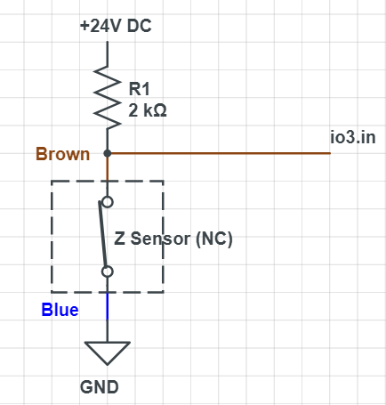
@dc42 Thanks for the info. I have created a circuit as below. The brown and blue wires represent the two wires from the switch/sensor.

I have tested the voltage between io3.in and GND using a multimeter. When the Switch is not pressed, the reading is about 1.8V, and when the switch is pressed, the reading changes to 19.8V
I have configured a Z probe in config.g as follows:
; Z Probe
M558 K0 P5 C"!io3.in" ; Z-probe tool setter connected to io3.in pin
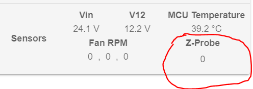
However, when the value of the Z probe in DWC doesn't seem to change. It just stays at 0. Even manually pressing the switch to trigger it does nothing, but I can see the voltages change in the multimeter

Any suggestions as to why the Z probe value in DWC is not changing?
I plan to use M585 to determine Z height during probing.
-
@RockB said in Z tool pre-setter sensor wiring:
K0
since you've defined K0 you must include a K0 in all other references to the probe usage and configuration. Eg G30 K0
If you only have a single Z probe, just leave the K0 off entirely.
-
@Phaedrux Understood, but the issue seems to be the Z probe not changing value in DWC even with manual triggering. The documentation says to expect 0 when not triggered and 1000 when triggered.
Checking the voltages using a multi-meter, I can clearly see the change from 1.9V to 19.8V with manually pressing the Z probe/switch.
Any suggestions on what is going on and why the Z probe value is not changing?
-
@RockB it's possible the probe triggers and the print head lifts fast enough after triggering that DWC doesn't update the display
-
@oliof Thank you for the suggestion but there is no print head movement in this test. I am pressing the switch manually and actually holding it pressed for a few seconds. Still no change in Z probe reading shown in DWC and also in Object model.
-
Firmware and DWC version?
-
@Phaedrux FW and DWC both at 3.5.2
-
@RockB io3.in expects between 0V and 3.3V to trigger it, but has a threshold somewhere between (probably around 1.5 or 1.6V) between being not triggered and triggered. If you're getting between 1.9V and 24V, io3.in will be permanently triggered. The
!in the pin definition inverts this, so it is permanently NOT triggered. Did you add the 330 ohm resistor between io3.in and GND, as @dc42 suggested? This should pull down the 1.8V to 0V.Does the LED light up on the switch?
Ian
-
@droftarts Ian, I tried adding the 330 ohm resistor between io3.in and GND - this causes the original 19.8V to drop to 3.2 V when switch is pressed (open); however in its closed (default) condition the voltage just drops from 1.9V to 1.8V. So now I am getting voltages in the range 1.8V to 3.2V and the lower voltage is still higher than the threshold for input pin.
LED does light up on the switch when powered (default state is NC) and goes off when pressed (open) as it should.
Any suggestions on how to further reduce the lower voltage so that it’s below the threshold? A circuit diagram would be helpful.
-
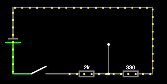
@RockB I think you misunderstood @dc42's suggestion. It should be 24V > Switch > 2.2k resistor > io3.in > 330 ohm resistor > GND, ie a voltage divider circuit. Something like this:

The wire between the resistors connects to io3.in. Here's a circuit simulation: https://tinyurl.com/233sf6pk
With the switch closed, io3.in gets 3.3V. When it's open, it's not connected, so should be 0V.Ian
-
@droftarts Ah! This makes sense. Will give this a try. Thanks
-
@droftarts Tested this and works as expected. Just changed the 2K resistor to a 2.7K resistor to limit the overall current below 10mA. Thanks
-
 undefined Phaedrux marked this topic as a question
-
 undefined Phaedrux has marked this topic as solved