Toolboard 1LC troubles
-
@Arminas is the blower fan that goes to 100% the hot end heatsink fan, or the print cooling fan? If there is a temperature reading error on the hot end then it's normal for the hot end heatsink fan to go to 100%. The firmware does that because it doesn't know what the temperature is, and having the heatsink fan on may prevent the hot end from clogging or getting damaged.
My best guess is that either there is a problem with the temperature sensor, or the temperature reading input on the tool board has been damaged by either a short circuit between the thermistor and heater wires, or by electrostatic discharge. So I suggest you start by checking the thermistor using a multimeter. Check that its resistance at room temperature is as expected, and check that there is no continuity between it and the heater wires. If that looks OK, try using the second temperature connector on the tool board. Make sure that the hot end metalwork is connected to Duet ground, either directly or through a resistor, to prevent static charge from building up.
-
@dc42 it's the blower fan. Temp sensor is good by checking it with multimeter. Is it possible that toolboard temp reading input is damaged and it causes the toolboard to do weird things, like over extrusion and etc.?
What do you mean by checking the continuity between temp sensor and heater wires?
Hot end metalwork is not grounded I guess. How do I do that?
-
@dc42 Same happens with second temperature connector. It just starts over extruding out of nowhere..
idk if this helps, but here is M122 B121:
M122 B121 Diagnostics for board 121: Duet TOOL1LC rev 1.1 or later firmware version 3.4.6 (2023-07-21 14:17:33) Bootloader ID: SAMC21 bootloader version 2.4 (2021-12-10) All averaging filters OK Never used RAM 2532, free system stack 31 words Tasks: Move(notifyWait,3.1%,99) HEAT(notifyWait,10.7%,75) CanAsync(notifyWait,0.0%,59) CanRecv(notifyWait,0.8%,74) CanClock(notifyWait,0.5%,65) ACCEL(notifyWait,0.0%,61) TMC(delaying,84.4%,57) MAIN(running,22.1%,351) IDLE(ready,0.0%,26) AIN(delaying,138.0%,142), total 259.6% Last reset 28:02:20 ago, cause: software Last software reset data not available Driver 0: pos 7263403, 415.0 steps/mm,standstill, SG min 0, read errors 3, write errors 2, ifcnt 20, reads 18793, writes 6440, timeouts 12343, DMA errors 0, CC errors 6419, failedOp 0x06, steps req 17729885 done 17729885 Moves scheduled 269100, completed 269100, in progress 0, hiccups 13, step errors 0, maxPrep 747, maxOverdue 130, maxInc 67, mcErrs 0, gcmErrs 0 Peak sync jitter -5/13, peak Rx sync delay 225, resyncs 0/0, no step interrupt scheduled VIN voltage: min 20.9, current 23.7, max 24.3 MCU temperature: min 41.9C, current 71.1C, max 76.4C Last sensors broadcast 0x00000002 found 1 157 ticks ago, 0 ordering errs, loop time 1 CAN messages queued 2019442, send timeouts 0, received 1178017, lost 0, free buffers 37, min 34, error reg 110000 dup 0, oos 0/0/0/0, bm 0, wbm 0, rxMotionDelay 974, adv 15860/74653 Accelerometer: LIS3DH, status: 00 I2C bus errors 0, naks 3, other errors 0 -
@Arminas said in Toolboard 1LC troubles:
MCU temperature: min 41.9C, current 71.1C, max 76.4C
Are you using a heated chamber?
-
@Phaedrux no, this printer is not enclosed. And I have one more RatRig Vcore 400 printer with 1LC, but this one is enclosed and there are no problems
1LC temp readings on enclosed printer are the same:
MCU temperature: min 19.6C, current 72.4C, max 75.2C -
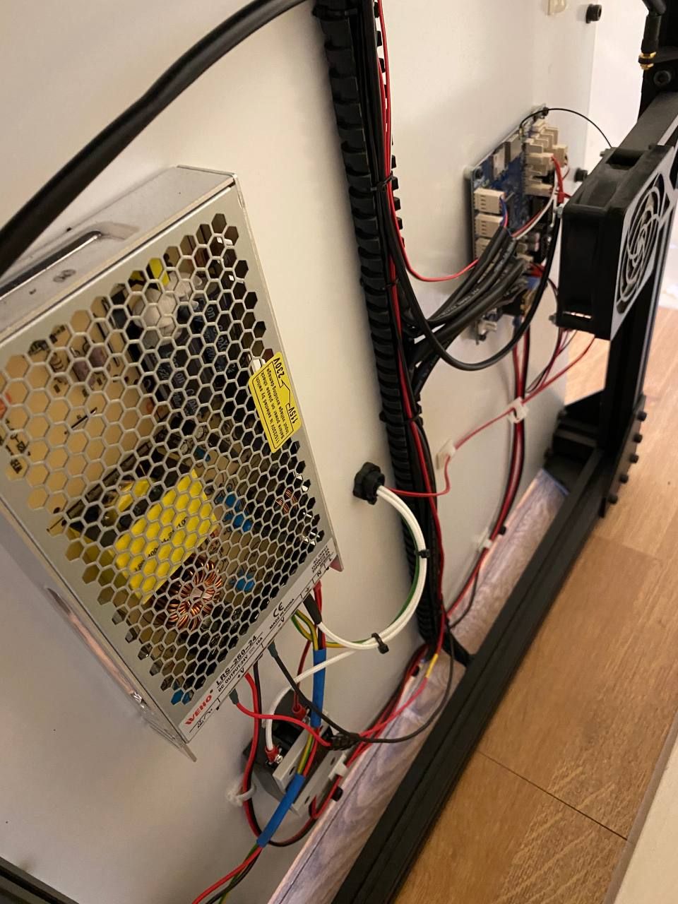
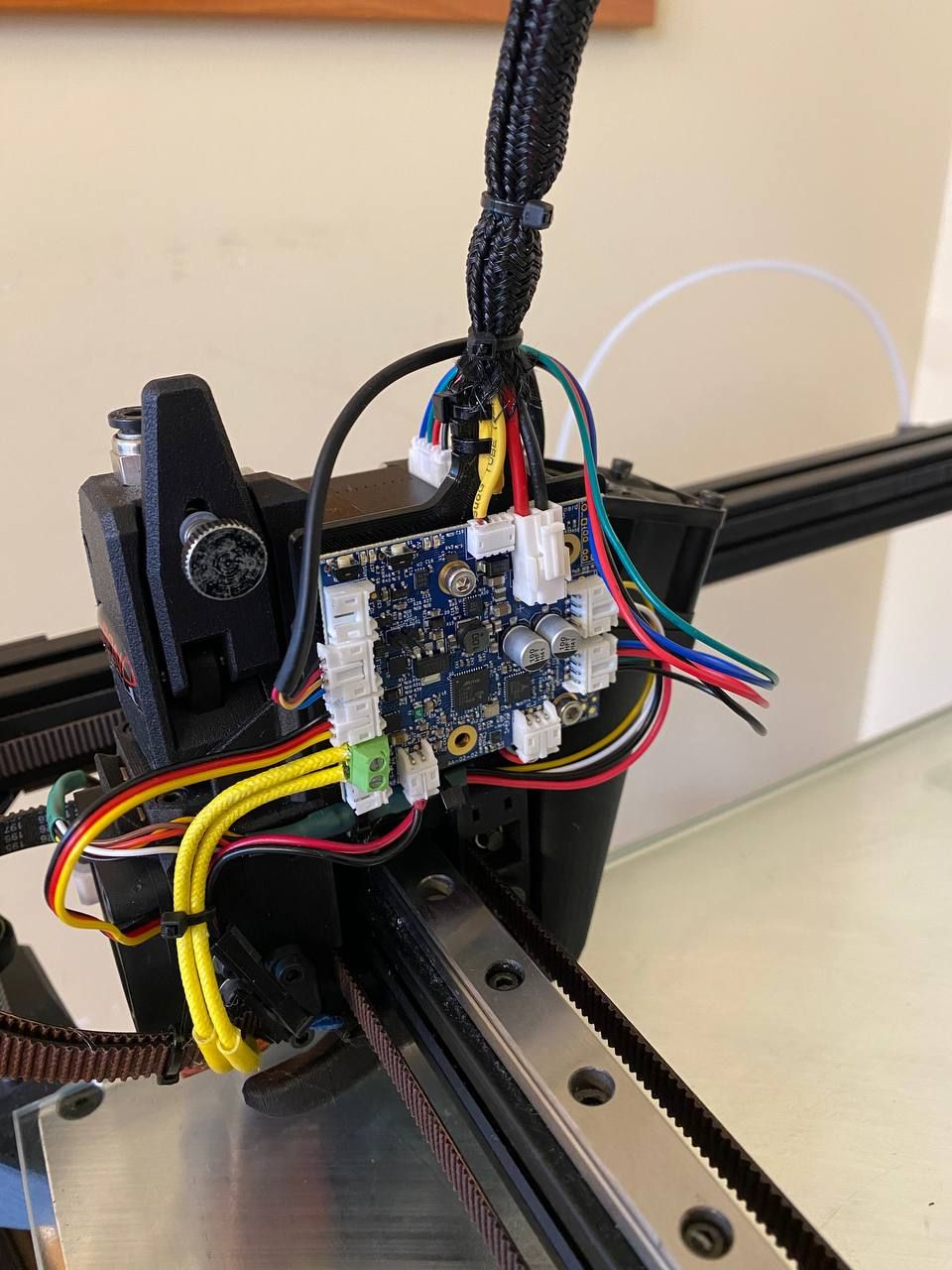
Those temps seem very high for a non-enclosed printer. Can you share some photos of the setup?
-
@Phaedrux Sure, here it is.


-
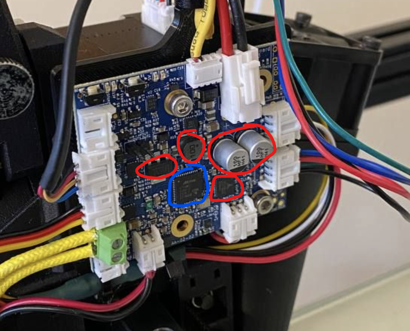
Can you tell if there are any components on the board getting very hot?
-
@Phaedrux Blue - cold, Red - hot (I don't feel comfortable touching it more than 3 seconds). And extruder motor is very very hot

-
Can you disconnect the motor and anything connected to the IO connectors, and see if it still gets hot?
-
@Phaedrux one of IO is used for BLTouch, I can't start the print without it. Maybe it's not a big deal if I leave this one connected?
-
@Phaedrux @dc42 @oliof Unfortunately, I think I have recreated the main issue with my other printer with exactly the same setup.... I have touched the nozzle with tweezers and I think something shorted due to static discharge. Blower fan immediately started to blow at 100% speed instead of 20%.. And now I have "hotend offline" in my DWC...

"On the v1.3 toolboard the mounting screw holes are all grounded via 100K resistors to provide a path to ground for any static build up in the extruders, assuming the toolboard is mounted to the extruder" - so if any of 1LC mounting bolts touches the extruder motor, I can simply wire a hotend with one of the mounting bolts?
Also, am I right that I can ground hotend to any duet GND pin? I would also ground the hotend of my Modix printers, but there is no toolboard. So I would connect the wire from hotend to Duet2 Wifi ground pin.
-
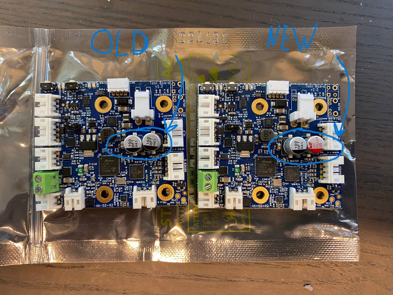
@dc42 Hi. I have purchased a new TB 1LC to try to swap it and see if the problem is still there. And I noticed that one component on old and new board is different. Both boards are v1.3, both with 202305-xxx code. Could this be an issue?
 image url)
 -
@Arminas I wouldn't worry too much about the different capacitors, I expect they are interchangeable. I have a v0.6 toolboard here with two black ones, and a v1.2 and v1.2a with one black and one red one. I thought I had a v1.3, but can't find it at the moment. The pictures on the documentation page also show this variation: https://docs.duet3d.com/Duet3D_hardware/Duet_3_family/Duet_3_Toolboard_1LC
Ian
-
@droftarts Okay. So as I understand, I had a short circuit due to static charge and it damaged the 1LC. I have grounded my hotend with simple wire to the printers frame. Frame is grounded. I checked the continuity between hotend and power sockets ground pin. But I still can see a spark after I touch the nozzle with tweezers. How can it be? Building's ground is not working?
-
@Arminas How is the frame grounded? It should be to the negative side of the power supply. If you're grounding the frame, it shouldn't rely on the frame itself to conduct, ie use a 'star' wiring layout, where all ground wires come to one point on the frame, with a wire to the PSU negative terminal. Check continuity of the ground from the hot end to the PSU negative.
Alternatively, wire the hot end ground to a mounting screw on the toolboard, or the toolboard's GND pin.
Ian
-
@Arminas just to confirm there is no issue with the electrolytic caps. you pointed out. Both types meet the specification for those parts.
-
@droftarts Okay, I might need some more explanation on this
 I have grounded the frame to the power socket's ground pin. As I was assembling the printer, there where an instructions to ground the bed to the PSU ground, and from PSU ground to power socket ground pin, so bed is grounded like per instructions.
 -
@droftarts Is there a way I can check if the TB 1LC is actually permanently damaged or not?