Duet 3HC Expansion looses Connection
-
@T3P3Tony , @dc42 , @droftarts
Individual Bench Testing: Interesting discovery
- My first 6XD with RRF 3.5 rc3 works with 3HC1 but doesn't work with 3HC2, 3HC3, or 3HC4 but the second replacement 6XD works with 3HC2, 3HC3, or 3HC4 but not 3HC1 . How is that possible. Same cable (Phone Cable (4m) testing)
same RRF 3.5 rc3 firmware and same cable , Same bootloaders Ver 2.8 on 3HC boards. The SD Cards are a copy of each other. They have same files .
Is there anything on 6XD Version 1.01 Board that would cause this kind of issue ?
-
6XD (Initial Board) ===> 3HC1 (with CAN Bus termination ) ===> Works and Syncs without Errors
-
6XD (Initial Board) ===> 3HC2 or 3HC3 or 3HC4 (with CAN Bus termination ) ===> Does not Work and Do not Sync
-
6XD (Replacement Board) ===> 3HC1 (with CAN Bus termination ) ===> Does not Work and Do not Sync
-
6XD (Replacement Board) ===> 3HC2 or 3HC3 or 3HC4 (with CAN Bus termination ) ===> Works and Syncs without Errors
-
@developeralgo222 Thanks for doing the continued testing. I don't have an explanation for the behaviour, but it seems like there's something amiss with the initial 6XD and 3HC1. Have you already asked for a warranty replacement of 3HC1, as @T3P3Tony suggested in his earlier post here https://forum.duet3d.com/post/333134 ?
Ian
-
@droftarts said in Duet 3HC Expansion looses Connection:
@developeralgo222 Thanks for doing the continued testing. I don't have an explanation for the behaviour, but it seems like there's something amiss with the initial 6XD and 3HC1. Have you already asked for a warranty replacement of 3HC1, as @T3P3Tony suggested in his earlier post here https://forum.duet3d.com/post/333134 ?
Ian
Not yet. i was puzzled as to why 2 x 6XD boards would behave so differently while everything else is the same on the them. i also wanted to make sure that the Boards with issues , actually did not work and were defective.
Until i can have all the 4 x 3HC Expansion boards individually working with 6XD Mainboard plus having them all connected in CAN bus Net and that can be repeated with Different cables then i don't think i have any confidence at all putting them in Production on a major project.
I love the Duet Boards, Duet Open Source Project and the options offered by them but i am not gaining any confidence in the reliability of boards. I might just be unlucky and got a bad batch, what are the chances of getting 2 x 6XD boards plus 2 x 3HC might not be working correctly out of 6 boards (2 x 6XD, 4 x 3HC ) ?
MainBoard 6XD Firmware: RepRapFirmware for Duet 3 MB6XD version 3.5.0-rc.3 (2024-01-24 17:59:29) running on Duet 3 MB6XD v1.01 or later (standalone mode) 4 x 3HC Firmware and BootLoader Duet EXP3HC rev 1.02 or later firmware version 3.5.0-rc.3 (2024-01-24 17:53:31) Bootloader ID: SAME5x bootloader version 2.8 (2023-07-25) -
I don't have an explanation for the behaviour
How is that possible. Same cable (Phone Cable (4m) testing)
The CAN bus is known as robust and error-proof, even with poor cables and in harsh environments. Why on earth does this special setup want to prove us wrong? Well, let me remind you of how this all began:
Remember the famous yellow line linking V– of both PSUs together? Before being told to add that, 3 boards were supplied by one, 2 boards by the other PSU, delivering 24V each, but without any common point of reference…
Between the PSUs, the voltage levels were undefined, or, for a better understanding of what might have happened in this case, can be assumed to having been quite high.
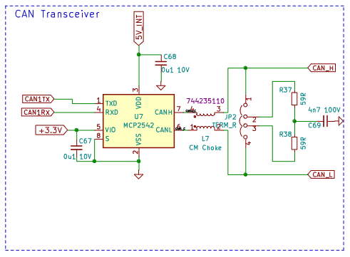
With CAN cables added, the potentials start to interact, currents flow along complex paths (see the schematics above) to establish some sort of common GND. Neither CAN ”H” nor ”L” are directly linked with V+ or V–, but: both lines go across all boards.
In other words: given the undefined potentials between two groups of boards, the voltages were negotiated via the CAN circuits - every single IC (MCP2542) or discrete component along the lines can be affected.
The ”soft” appearance of the fault(s) can be plausibly explained with a ”low current, high voltage” event, similar to what happens intentionally in EEPROMs. Else, we could observe burnt resistors or visibly damaged ICs.
Further evidence of subtle effects of the kind I described above is given by the fact that the problem spreads across at least 2 boards and depends ”somehow” on cable lengths - as if the CAN circuity has developed some kind of ”antenna sensitivity”.
@developeralgo222 said in Duet 3HC Expansion looses Connection:
I love the Duet Boards, Duet Open Source Project and the options offered by them but i am not gaining any confidence in the reliability of boards. I might just be unlucky and got a bad batch, what are the chances of getting 2 x 6XD boards plus 2 x 3HC might not be working correctly out of 6 boards (2 x 6XD, 4 x 3HC ) ?
Instead of spreading doubts about the quality of the boards or the engineering capabilities, better use Ockham's Razor: a single cause of failure is more likely to happen than multiple problems across multiple boards at once.
-
@infiniteloop said in Duet 3HC Expansion looses Connection:
I don't have an explanation for the behaviour
How is that possible. Same cable (Phone Cable (4m) testing)
The CAN bus is known as robust and error-proof, even with poor cables and in harsh environments. Why on earth does this special setup want to prove us wrong? Well, let me remind you of how this all began:
Remember the famous yellow line linking V– of both PSUs together? Before being told to add that, 3 boards were supplied by one, 2 boards by the other PSU, delivering 24V each, but without any common point of reference…
Between the PSUs, the voltage levels were undefined, or, for a better understanding of what might have happened in this case, can be assumed to having been quite high.

With CAN cables added, the potentials start to interact, currents flow along complex paths (see the schematics above) to establish some sort of common GND. Neither CAN ”H” nor ”L” are directly linked with V+ or V–, but: both lines go across all boards.
In other words: given the undefined potentials between two groups of boards, the voltages were negotiated via the CAN circuits - every single IC (MCP2542) or discrete component along the lines can be affected.
The ”soft” appearance of the fault(s) can be plausibly explained with a ”low current, high voltage” event, similar to what happens intentionally in EEPROMs. Else, we could observe burnt resistors or visibly damaged ICs.
Further evidence of subtle effects of the kind I described above is given by the fact that the problem spreads across at least 2 boards and depends ”somehow” on cable lengths - as if the CAN circuity has developed some kind of ”antenna sensitivity”.
@developeralgo222 said in Duet 3HC Expansion looses Connection:
I love the Duet Boards, Duet Open Source Project and the options offered by them but i am not gaining any confidence in the reliability of boards. I might just be unlucky and got a bad batch, what are the chances of getting 2 x 6XD boards plus 2 x 3HC might not be working correctly out of 6 boards (2 x 6XD, 4 x 3HC ) ?
I agree with you. i believe that its not the cables. And your explanation makes sense but if you have 2 PSUs that are feeding 5 boards (2 on PSU and 3 on the other ) and they are both grounded and those duet boards accept upto 24V. The initial missing connection (Jumper wire) between V- on PSU1 (24V,20A) to V- on PSU2(24V,20A) would have only affected the CAN synchronization of the Boards . Not sure why ? if they are connected independently to their respective PSU then boards would be damaged ?
Note: The Isolated test bench has 1 PSU only, 5 Boards (6XD, 4 x 3HC) , with only VIN & GND and CAN Bus with termination connections. This is to individually test each 3HC for functionality before putting them into a CAN Bus Network.
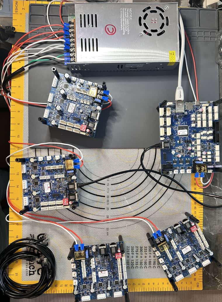
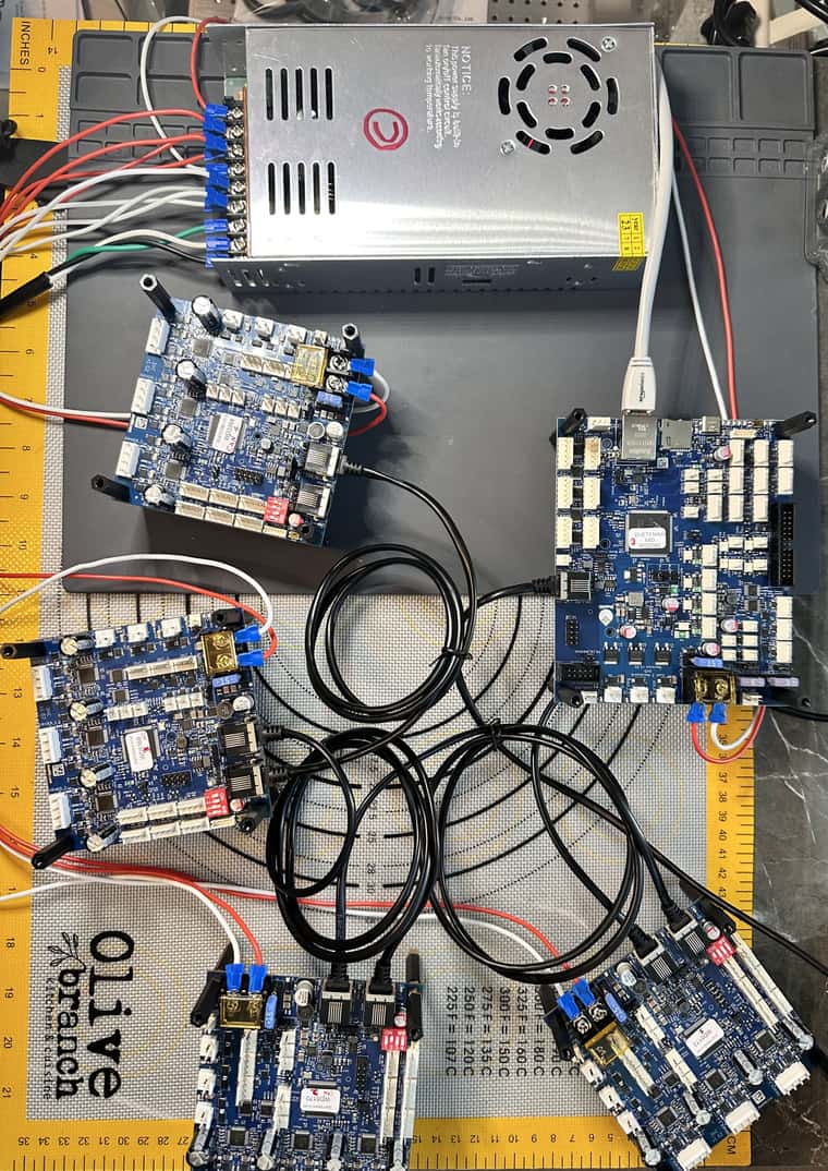
In other words: given the undefined potentials between two groups of boards, the voltages were negotiated via the CAN circuits - every single IC (MCP2542) or discrete component along the lines can be affected.
Does that mean we have an issue with the way the CAN-FD is designed on the Duet Boards ? Does Duet boards have some protection designed in them to mitigate that issue ("undefined potential") as per your explanation above ?
-
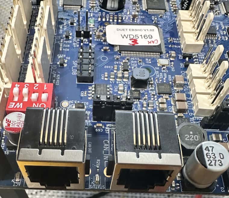
@developeralgo222 Can you grab some photos of the can sockets?
-
@Phaedrux said in Duet 3HC Expansion looses Connection:
@developeralgo222 Can you grab some photos of the can sockets?
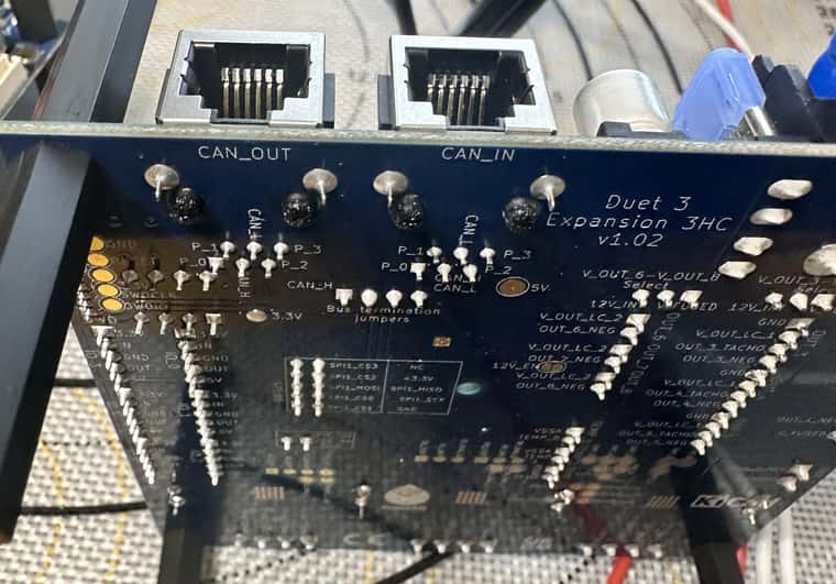
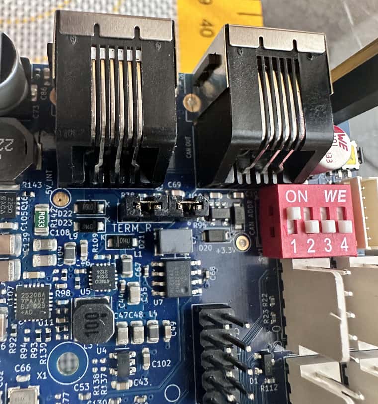
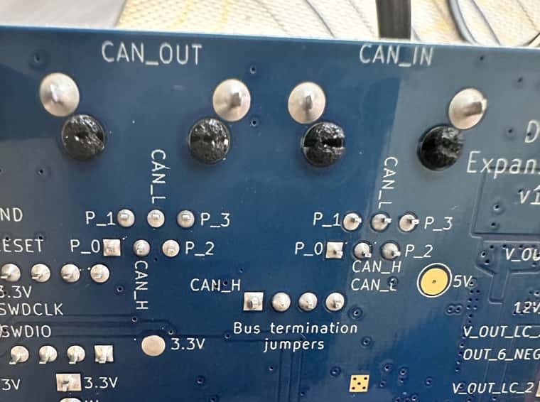
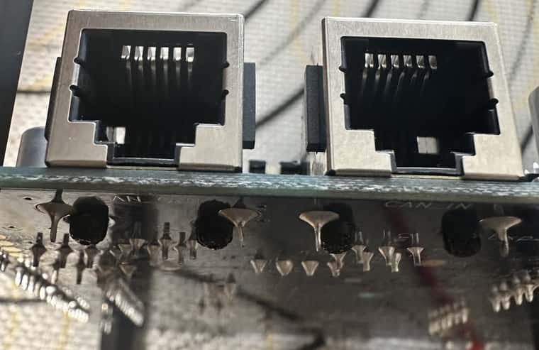
-
That's the number 3 3HC?
-
@Phaedrux said in Duet 3HC Expansion looses Connection:
That's the number 3 3HC?
Yes , 3HC3 and at least 1 photo for 3HC1
Expansion Boards 3HC3 and 3HC1 seem to be the boards that might be having some issues.
All i really need is for this boards to be able to work. FYI, i am not blaming anyone or looking to blame Duet3D. I am just asking questions per the testing of the boards setup. The tests reveal a few things that don't match what Duet Support expects. I would be more than happy to work with anyone quickly to have the Duet Boards working.
-
@T3P3Tony said in Duet 3HC Expansion looses Connection:
@developeralgo222 ok so it does look like that 3HC needs replacing as well. please follow the same process as before with an email to warranty@duet3d.com. I suspect the 6XD may actually have been ok, but we will have to see when we get ti back for testing.
Have sent an email to warranty@duet3d.com to have 2 x 3HC boards swapped ( Boards 3HC1 & 3HC3 ) . This boards don't seem to work correctly. Only Boards 3HC2 & 3HC4 work correctly with 6XD Mainbaord (replacement) and all cables tested including Kenable ADSL 2+ cables.
So far using any kind of recommended cable (Kenable ADSL 2+) or self-made cables as per the requirements, the only reliable and consistent results (Only with 1 PSU---24VDC, 20A) on the
-
Isolated Test Bench have been:
-
6XD(replacement) ====> 15m/1m (Kenable ADSL 2+ Cable) ====> 3HC2 (With CAN Bus Termination) =====> Works and Syncs without errors
-
6XD(replacement) ====> 15m/1m (Kenable ADSL 2+ Cable) ====> 3HC4 (With CAN Bus Termination) =====> Works and Syncs without errors
-
6XD(replacement) ====> 15m/1m (Kenable ADSL 2+ Cable) ====> 3HC2 ===> 1m (Kenable ADSL 2+ Cable) ====> 3HC4 (With CAN Bus Termination) =====> Works and Syncs without errors
Even reversing the Cable length order or 3HC expansion boards order , that still works
- PnP Machine : The above results have also been duplicated on the PnP Machine without errors so far.
-
-
@developeralgo222 I don't know, and we probably won't until the returned boards make their way back to us in the UK, if a ground loop has caused the CAN malfunction, but is there a particular reason why you want to use two power supplies? For a pick and place machine, you're only moving axes and switching relays, generally, so I doubt there is anything drawing particularly high current. Usually it is the bed heaters and hot ends on 3D printers that create the need for high current, or multiple, PSUs. It just seems like an unnecessary complication.
Have a look at this wiki page to calculate what your system might draw: https://docs.duet3d.com/en/User_manual/Connecting_hardware/Power_choosing
Ian
-
@droftarts said in Duet 3HC Expansion looses Connection:
@developeralgo222 I don't know, and we probably won't until the returned boards make their way back to us in the UK, if a ground loop has caused the CAN malfunction, but is there a particular reason why you want to use two power supplies? For a pick and place machine, you're only moving axes and switching relays, generally, so I doubt there is anything drawing particularly high current. Usually it is the bed heaters and hot ends on 3D printers that create the need for high current, or multiple, PSUs. It just seems like an unnecessary complication.
Have a look at this wiki page to calculate what your system might draw: https://docs.duet3d.com/en/User_manual/Connecting_hardware/Power_choosing
Ian
In reality , i don't think PnP will draw that much power (2 x Nema 34 closed loop motors with 2 external drivers, 3 x Nema 17 stepper motors directly on Duet 3HC , 6 x Nema 11 stepper motors directly on Duet 3HC). I am OK to use just 1 PSU (24V,20A ) but it might be cutting it a little close as per the actual power draw requirements and calculations. Once i have everything setup completely and working i will see the actual max power draw when the machine is in intensive PnP operation.
For now, both the Isolated Test Bench & PnP Machine , i am just using 1 PSU each to make things simple. I perform all the tests on the Isolated Test Bench and once a 3HC Board passes all tests then its moved and added to the working boards on PnP Machine and tested again to confirm that it works as expected on the PnP Machine and i will only add a second PSU if i am gettting close to 80% of the rated 20A (16A) on the PSU1.
-
@developeralgo222 said in Duet 3HC Expansion looses Connection:
Does that mean we have an issue with the way the CAN-FD is designed on the Duet Boards ? Does Duet boards have some protection designed in them to mitigate that issue ("undefined potential") as per your explanation above ?
Only optical insulation can provide this level of protection. This is usually done by optic fiber transceivers, and of course, optic fiber . These modules were not designed for such environments, nor they should/need to be. Except an human error, like in this situation, they should perform optimal, the way they are designed.
If CAN signal needs to be sent over long distances, and/or over big voltage differential, or in a really very, very noisy environment, only then such optical insulation is justified. In a machine like... most of ours, it is not the case. Working with 300kV (let say), for ozone generators, then we are talking another level, and then, those transceivers are justified.
Those undefined potentials, could very easy destroy some protection diodes, wich are calculated for a certain range, wich can be checked in chips specs. But the event ”happened” here, for sure surpassed the specs of the chips protection.
The interesting here is that the problem generated, can be (in appearance) very strange and inconsistent. One only can pray electronics boards to ”survive” after. In your case, you had not do it hard enough, if I may have a joke at this ”funeral”.
Sorry, but, no offence, I did not assumed too much. I myself done such stuff, so many more than once. Experience comes with a price ... usually.
L.E. The boards have a protection for common mode signals, L7, in a certain range of frequency.
However, adding a protection for what you would have needed, would mean (for example) some series resistors on the bus, to limit the current in the protection diodes (wich exists, inside the chips).
As the voltages may be relatively big (tens of volts or more, in this case with 2 PSU, without ground wire), the resistors should be in the range of (tens of?) kiloohms, wich would impair the speed of CAN so much, than it would not be usable for high speed communication (or even for low?), especially for somewhat longer cables, like 4-15m, as the parasitic capacitance will increase with length, but I suspect even for shorter ones it would be true.
Not to talk about adapting the bus (those terminators) in such a case...
In any case, nobody in the industry is doing such a thing, as it is not useful.L.L.E. Isolating CAN Bus
One may jump directly to Conclusions, but the paragraph about Sources of failure, is a good read too -
@developeralgo222 can you confirm that the replacement boards have solved the problem?
I have the two 3HC and one 6XD boards you returned set up on the bench and connected them together using two Kenable CAN cables. Both 3HC boards had the termination jumpers installed when they arrived, so I removed the jumpers on the middle board. They are all syncing reliably. I will look at the CAN signals on an oscilloscope later to check that the signal levels are correct.