Hollow shaft extruder
-
I just registered on simpleFOCs own forum and asked some questions.
There is a guy, who has build his own screw-extruder, his own (tiny!!) hotend and designed an STM32 based simpleFOC driverboard with encoder. Awesome guy!
Check out his video
He, amongst others, voted against building a toolboard with BLDC driver, but instead provide basic step/dir interface and use simpleFOC on a standalone board. -
@o_lampe
That was exactly what i was thinking of, but with a external counter.
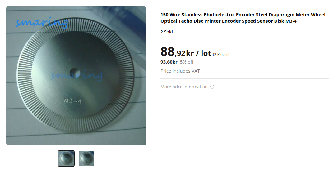
Give me a shout if you are thinking about ordering some of those boards. Can do all the soldering/flashing if needed. Don't have a resin-printer myself to print the extruder so maybe we can do a colab.Would probably be possible to use something existing like this instead of printing that disc. (steps and size would of course need to be matched with the extruder/motor/pcb)

-
@pakar
I'm not through with reading all the interesting stuff over there and they seem to be very active.
The sFOC-mini I've ordered is not the best solution (but it's the official PCB).
I'm sure we find a way to colab. I live in Germany, BTW.The slotted disk wouldn't work with his reflective sensor. I thought of making my own disk from black anodized and laser engraved aluminum. Or spray-paint/engrave a lighter plastic disk. My CO2 laser could then do both, cutting the shape and engrave.
-
@pakar said in Hollow shaft extruder:
12 coils and 14 magnets would get you to ~8.5°. The more coils/magnets you have the more "steps" you will have. This is why a encoder is "required" for anything with high accuracy.
Thanks @pakar. I have not explored the topology of BLDC motors so I have no idea how 12 coils and 14 motors would result in 8.5°. Part of me thinks wow, that's intriguing tell me more and part of me just wants to take it as read!
Anyway, with my VDE-100 that represents 0.035mm of extruder travel and I am pretty happy with that. More to the point, though, I think the most important thing with the extruder is speed, not absolute position.
-
@tombrazier said in Hollow shaft extruder:
the most important thing with the extruder is speed, not absolute position.
That's what they said, too. You could live with open loop, then it runs in velocity control,but the starting sequence is a lottery (my words). Not sure how well it behaves when changing direction for retract/unretract. Will there be a hiccup every time, or will the motor sync once and stay synced while powered?
-
@o_lampe I really like the stand alone board with the step/dir interface. Looks like it has not yet become mass produced by China.
-
Not sure how well it behaves when changing direction for retract/unretract. Will there be a hiccup every time, or will the motor sync once and stay synced while powered?
@o_lampe Same dynamics here as with stepper motors, I would think. M201 and M205 will need tuning.
-
@tombrazier The best about these boards (there is also a similar mosquito board):
they only use parts that are/were in stock! Quite a challenge, I can tell from my own experience. -
@tombrazier said in Hollow shaft extruder:
Thanks @pakar. I have not explored the topology of BLDC motors so I have no idea how 12 coils and 14 motors would result in 8.5°. Part of me thinks wow, that's intriguing tell me more and part of me just wants to take it as read!
14 pole, 12 stator = 7 * 6 = 42 steps = 8.571 degrees.
I of course assume that it's a 3-phase motor and the number of stators need to be a multiple of the number of the number of phases.I tried looking for a good introduction but only found this, and that may be a bit too much as a introduction.
https://what-when-how.com/electric-motors/stator-winding-design-considerations-electric-motors/ -
@o_lampe Of course. I'm fully booked with work right now so it won't happen in at least 2-3 months. I live in Sweden so fairly close

The one i posted was stainless steel as a reflector. Only a non-reflective background would be needed.
Other option is a non-reflective slotted disk with a reflective background.
But not sure what field of depth the sensor has so using a non-reflective disk with a reflective background may be problematic.Either way i would recommend using a disk-material that won't wobble too much with the vibrations.
If you got a laser that would be perfect, and cheaper!
-
Had my first simpleFOC project running today. It was an old brushless gimbal controller without encoders and with 8bit mcu.
I was able to control two motors independently and relatively smooth (USB power only)
The atmega328 was also at it's limit, but I'm now confident it will work well with the right mcu. -
@o_lampe What motor driver did you use?
-
@tombrazier The drivers on the old gimbal controller are L6234D.
Not the same type as the current DRV8301, but they were used to develop simpleFOC at the beginning. -
Today I had the first test with the step-dir interface of simpleFOC.
It was a bit of a learning curve to get it working with the magnetic sensor I had.
Running the motor in open loop is no option, the motor gets pretty hot.
In closed loop the motorcurrent is reduced to the actual required torque.
I wanted to give it a real-world extruder-test and ran a typical gcode, but with the XYZ steppers absent, I got tons of errors. (motorphase disconnected)
I wonder how I can get rid of those messages? -
@o_lampe set the motor currents on XYZ to 0, that should stop the errors
-
@o_lampe you could just connect some resistors with the same resistance as a normal stepper motor winding and set the current really low.
I'm guessing that shouldn't break anything and would fool the board into thinking a stepper is connected...Or just connect any random spare motors you may have lying around...
Just a thought...
-
Thanks all for the tips, it's running now.
Just had to add thermistors
It's fun to see the motor almost jump off the table when retracting
-
@o_lampe from another thread, courtesy of @chrishamm
If you set the motor current [...] to less than 500mA, you should not get any "phase disconnected" warnings even if you leave it disconnected.
-
@oliof Thanks, that's what I did.
And adding a thermistor, because I just took the SD-card from my Delta printer and wanted to keep the config.g as original as possible.It will take a while, before I can test the setup on any screw extruder, so I thought of a different way to test the BLDC in a real scenario.
What If I mount it to my sherpa mini instead?
-
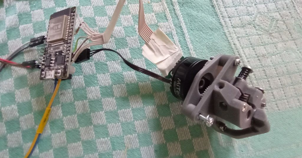
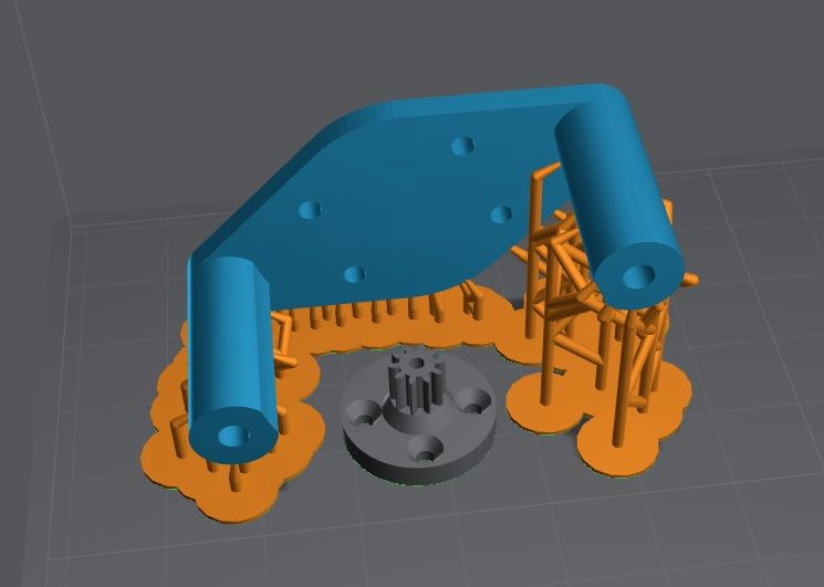
Guess, what's printing right now


Wondering how long the gear will last. In my harmonic drive experiments, they lasted a few days with a medium load.