Redesigned the MFM housing
-
@thooijer-0 said in Redesigned the MFM housing:
Thank you for the design , the original i printed skipped.
I noticed without connecting it to the duet.
It will probably work when printed with very tight parameters or with a resin printer.
Your design works good for me, have printed a few objects and it works fine.
Tested the runout function and it is really great! Thanks!

Thanks! I'm really glad it's working out.
-
 undefined infiniteloop referenced this topic
-
 undefined invertmast referenced this topic
-
@Lo-Fi said in Redesigned the MFM housing:
UPDATE 14-04-22: Now released here: https://github.com/KerbalFoundries/Duet-Magnetic-Filament-Monitor-Housings
Hello!
I'm fairly new to actively posting here, but been using Duet/RepRap Firmware for a while now and recently got tempted to buy a filament monitor after having one or two issues with long prints getting ruined. And because it's a cool little gadget. Who can resist a cool gadget, right?
To cut a long story short, I had a few issues. Some of those (sensorError) were due to loose crimps and something that got tweaked in one of the 3.4 release candidates that dc42 was kind enough to clue me in on. The other issues was "tooLittleMovement". After a while I figured out that I had a few issues with the printed case. In fairness, I know it's supposed to be resin printed really, but I don't have a resin printer. I do have some 3D CAD skills and a love of tinkering, so I set about first recreating the existing design, then tweaking it. Editing STL files is not my idea of fun, so I redrew it in OnShape.
I came up with a few design goals and tweaks:
-
Keep the filament path clear of anything but the PTFE inserts, hob and idler.
-
Align the PTFE so the filament is lightly pressed against the hob even before the idler comes into play
-
Add slightly more clearance for the hob and idler in the filament region
-
Add an indent to keep the idler spring in the correct position
-
Achieve a tight fit for the plastic collets holding the PTFE
The housing I came up with worked a treat, I'm happy to say.
Pic for comparison:
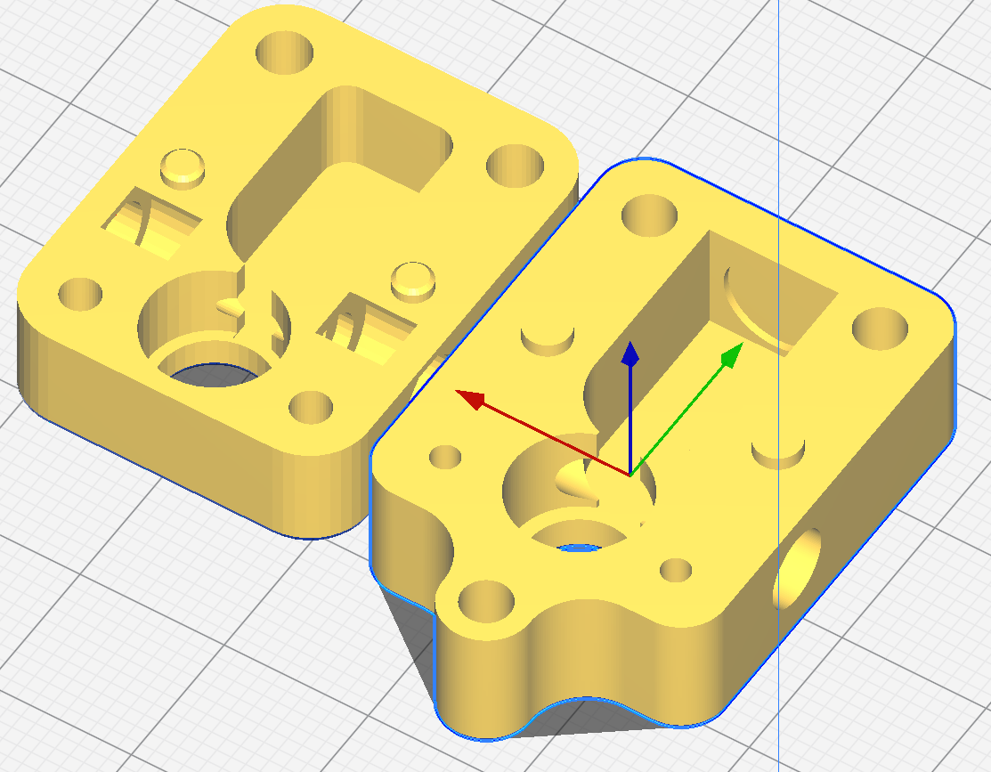
I felt an extra mounting lug couldn't hurt either.
Fast forward a little bit... I ended up spending some time on the forum and chimed in on a few threads where people had similar problems and shared my design a few times. It's a funny thing, though: Once I start sharing out stuff I create, it's hard not to want it to be a good as it can be.... I've been down this rabbit hole before making a KSP mod a few years back, but let's not get sidetracked! It's an enjoyable thing getting involved in an open source project/community, so why not?
I printed and tested many prototypes:

Given that this needs to be printable on any printer, the sane thing to do is print it on the worst machine possible. In my case, it's an ANET A8. I can hear what you're thinking... "You came in that thing?!? You're braver than I thought!" In my defence, it was my first printer, has been modified and runs RRF (though on a Fly CDY V3 - I hope I'll be forgiven, I couldn't justify a Duet for this one). However, it's got a horrid build bed and no bed compensation. Realistically a worst-case scenario for most people playing with Duet, I suspect.
Anyway, the point I'll get to is that I found it really had to hold the tolerance between the bottom of the lid and the stop of the standoff, which all other things being equal is what defines the distance between the sensor and the magnet. A well set up 3D printer can hold surprisingly good tolerances, with the bottom layer being one of the exceptions in a lot of cases. The solution that came to me was to make the standoffs part of the body, not the lid. The critical tolerances (bottom bearing flange seat, top deck of body, top of standoffs) are all then defined by the layer height tolerance without a first layer in the stack:
MK1:
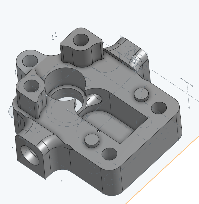
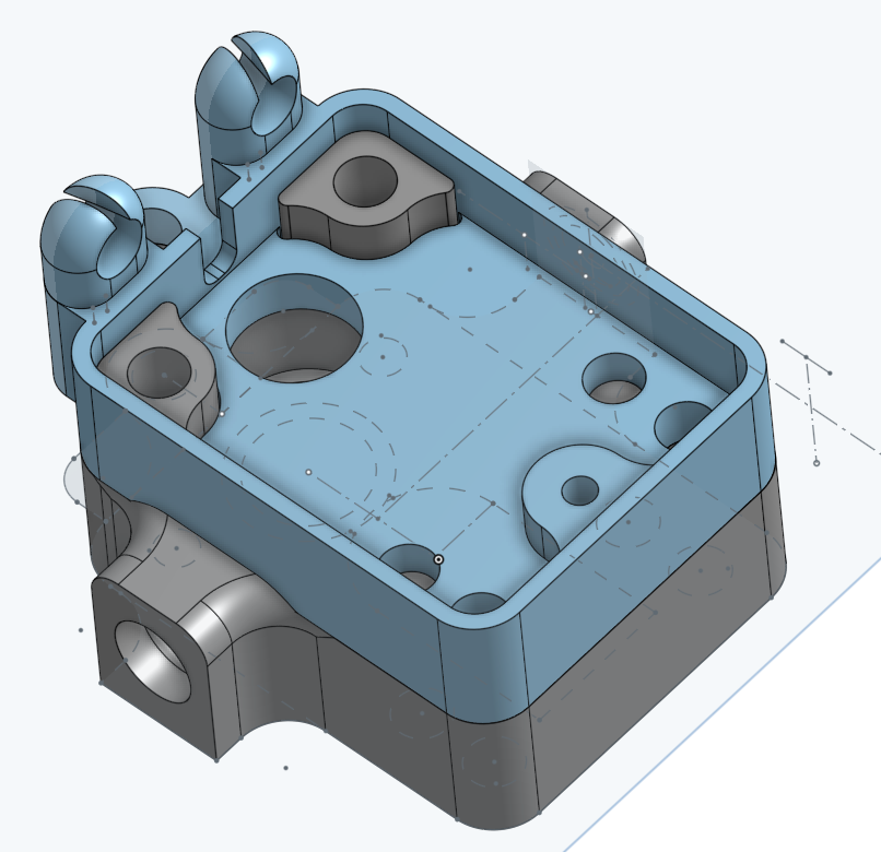
At this point, I should add that I have the MK1 rotating assembly. The MK2 has a shorter hobbed section and fatter magnet. Moving the deck of the body cuts into the reliefs for the PTFE collets, creating a gap where the collets can push the lid up. This didn't seem ideal, so I moved them out to some small extensions. This has the added bonus of giving more length within the housing to hold the PTFE nice and stable.
I made a few "quality of life" adjustments, making the bearing seats and PTFE holes slightly tapered for easy starting without resorting to files or suchlike.
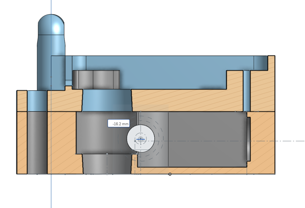
I had a quick think about the idler carrier. I'd designed with slightly more room for a beefier carrier, so came up with something that still allows the halves to be identical, but a little more surface area for the glue joint, and the joint running perpendicular to the layer lines for strength:
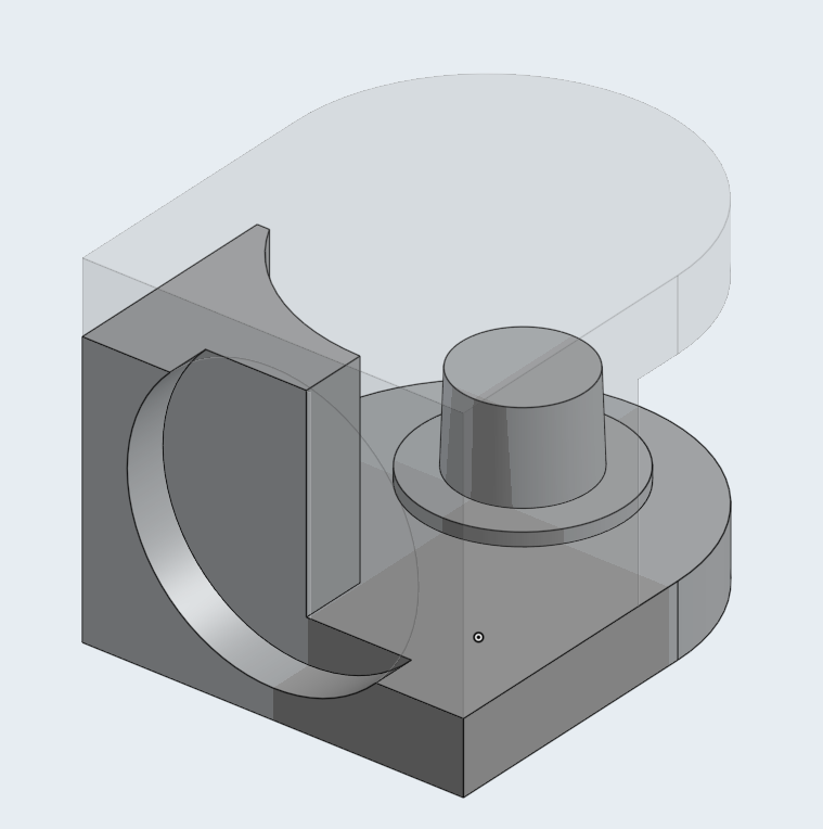
The result:


A quick view of how the standoffs work:


And the strain relief works nicely too:

All printed PLA, 0.1mm layer height, 3 walls, 0.4mm nozzle, 0.4mm line width on a cr**tacular printer
and snapped together with nothing more than a light deburr. M591 D0 from its first print:Duet3D rotating magnet filament monitor v3 on pin e0stop, disabled, sensitivity 26.67mm/rev, allow 70% to 130%, check printing moves every 6.0mm, version 3, mag 131 agc 86, measured sensitivity 26.62mm/rev, min 95% max 104% over 5150.3mm
That's probably accurate. That print was 0.6mm line width, 0.3mm layer height and fairly fast. Just happened to be what came up for printing when the latest prototype was ready. Typically, I'd expect and get 98%-101% on a more standard 0.4mm width .1 or .2mm layer print. I'm happy enough with the mag and agc right there straight out of the box. Yes, it's disabled for the moment. I tend to log M591 for a few prints before sending new designs live in case it starts doing weird stuff and pausing prints that it shouldn't.
I've got some testing to do to make sure this really is as solid as I hope and have been in touch with one of the team about getting hold of a V2 rotating assembly to make sure that version is working nicely too.
I'll start sharing links in a couple of days when I'm sure it's all behaving. I hope I'm not treading one anyone's toes - I figure this is all in the spirit of open source
Thanks for reading!
Excellent job! Would it br possible to have the STEP files (or Fusion360 files) for the V2 Assembly? Id like to make some adjustments to fit it in my printer.....
Thanks!
-
-
@TheDragonLord
Hi, just found your post - sorry for the delay and thanks! I don't use Fusion so STEP is the best I can do:
-
@Lo-Fi said in Redesigned the MFM housing:
@TheDragonLord
Hi, just found your post - sorry for the delay and thanks! I don't use Fusion so STEP is the best I can do:
excellent, thanks
-
What‘s the difference between V1 and V2? Does it depends on the version of the magnetic filament sensor. I have 1.7b… What should I use?
Thank you for your great job,
Pierre -
No more support needed! Another happy user of the magnetic rotary filament sensor with your housing! After 1,5 years of frustration and useless parking… Thank you so much!
Kindly regards, Pierre
-
Apologies for the slow reply! Glad it's working out for you

-
I am trying to print this redesigned housing, but I cannot get open the V2 stl files. Have tried simplify3D, cura and mesh maker. I think the source may be corrupted. Does anyone have working versions of them?
-
@Dave-Parry Where and how did you download the files? Github can be tricky, you must right click on the RAW button and save as...
-
@Phaedrux Thanks, thats what I did, But would'nt open in anything.
Have managed to import the step files into inventor and then save those as STL's. Just printing them now. Fingers crossed.
The V1 files also wouldnt open, but there is a link above that worked, but my magnet is 2mm so I think it's V2 -
Hello,
Great job with this housing design, it works way better then the original housing but I have one request. Would it be possible for you to modify the exit side of the filament hole in the housing so that it tapers from the hole size you have at the start down to the ID size of the exit tube. I find that the filament gets stuck on the edge of the tube more times than not. I could modify my own housing if I had the cad file.Thanks
-
@thaug29 They are designed in OnShape, and available here: https://cad.onshape.com/documents/411d70b025239cbb231798cd
I don't think @Lo-Fi has done a V3 version yet.Ian
-
@droftarts Ok, thanks I will check it out and see what I can do.
-
 undefined droftarts referenced this topic