Duet3, microswitch endstops - why connect GND to io[x].in?
-
Technically I don't need to ask questions, I can just what this says:
...but I'm curious.
Why not connect one of the voltage supply pins to the input?
Is it because io[x].in will start working as output as soon as it is configured for use as endstop? And that, in turn, to get the benefit of the larger value resistor?
(Thanks)
-
@piotrkmiotczyk It's for safety. The input pins are tied to permantent pull-up resistors, so if the connection GND <-> IN, which should be normally-closed, is interrupted unexpectedly (broken wire), the machine stops immediately.
-
@piotrkmiotczyk there are layers and layers of 'why'.
Why you connect a homing switch on a 3D printer so that it's normally 'on' (ie the input is normally tied to ground) is as chrishamm says - so that if it becomes disconnected the machine stops because it thinks it's at the endstop.
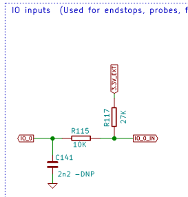
Why the 'normally on' is to ground (rather than to +ve supply) is because that's how the Duet boards are designed - there's a pullup resistor on the input so a disconnected switch goes to +ve (actually 3.3V), so you need to arrange the switch connected to ground (0V). See e.g. this snippet from the Mini5 schematic:

Here IO_0 to the left is what goes to the chip, and IO_0_IN to the right is what goes to the pin on the connector. The R117 is the pullup resistor, so if the switch is open the chip 'sees' 3.3V, and if the switch is closed (and connected to 0V) the chip 'sees' 0V. If you connected the switch to 3.3V, the chip would always 'see' 3.3V.Why the boards are designed that way is (probbaly) because that's the normal way it's done - most microprocessor switch inputs are configured this way, with a switch and resistor arranged that when open the chip sees +ve supply due to a pullup resistor and the switch connected to ground so that when the switch is closed the chip sees 0V. See most Arduino or Raspberry Pi or similar introduction to electronics tutorials - this is how it's normally done.
Why this is normal is - dunno. Possibly it's because you more normally have multiple 0V points and lines on a board so it's often easier to get a 0V wire / signal to a switch than it is to get a +ve supply wire. There's often no really good reason - if you were designing the circuit yourself you could use a switch with a pull-down resistor and the switch connected to +ve - then the chip would see 0V when the switch is open, and +ve supply when the switch is closed.
Some chips have built-in pullup resistors, so with this configuration you don't need a separate external resistor, but I think that's mainly because this is the normal way it's done. That is, the chip designers have done that in reaction to this being the normal approach, not that this is the normal approach because that's how the chips are designed. (Some chips have both pull up and pull down - and some have differnet strengths in each direction, but again, I think that's a result not a cause.)
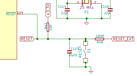
Also, many (and I think probably most) configuration inputs to chips are arranged like this so 0V means 'active' - for example chips that have a 'select' line to make them do something are often/usually designed so that making that input 0V selects them. It will normally be shown as 'CS' with a line across the top of letters - meaning 'chip select active low' (because the letters are below the line, ie low). Or reset lines are often designed to reset the chip when the input is forced to 0V. The chips on the Duets show that too, see e.g.:

So here, the chip resets if that input is forced to 0V, so the board has a resistor (R47) pulling it up to 3.3V and there's a switch that forces the line to 0V when it is closed.This does have some good reasons behind it (to do with asymmetries in semiconductor physics - much the same ones as to why we normally use low side switching transistors), but only for early chip designs (mostly obsolete). However, early chips did it that way for good reasons, and newer chips do it that way because that's the way the all the other chips do it.
-
@piotrkmiotczyk it's better to have ground wires running to endstop switches rather than wires carrying +3.3V or +5V or some other voltage, in case they get accidentally connected or shorted to another wire or the frame of the machine.
-
Thank you! I've learned a lot.
What a friendly forum.
I admit these some of these are the basics, or basic conventions, of microcontroller use, but I just didn't have an opportunity to learn them earlier.