Sammy C21 support for 2 TMC2209 drivers with UART com
-
@dc42 said in Sammy C21 support for 2 TMC2209 drivers with UART com:
We don't yet have a board that uses more than one TMC2209 and does not have a multiplexer (which is needed to handle more than 4 drivers), that's why we have never built this combination before.
Yes, though It's great that it's this configurable. Quite impossible to test every permutation.
Big thanks for taking the time to look at this which is obvisously outside your current scope.However, with the changes I did in Platform.cpp it now builds without errors but it seems to crash directly it's loaded onto the Sammy.
If you would have the time sometime to quickly see if I've made something obviously stupid here (I'm sorry I can't get the tabulation correct here):
/* * SAMMYC21.h * * Created on: 23 May 2020 * Author: David */ #ifndef SRC_CONFIG_SAMMYC21_H_ #define SRC_CONFIG_SAMMYC21_H_ #include <Hardware/PinDescription.h> #define BOARD_TYPE_NAME "SAMMYC21" #define BOOTLOADER_NAME "SAMMYC21" // General features #define HAS_VREF_MONITOR 0 #define HAS_VOLTAGE_MONITOR 0 #define HAS_12V_MONITOR 0 #define HAS_CPU_TEMP_SENSOR 1 #define HAS_ADDRESS_SWITCHES 0 #define HAS_BUTTONS 1 // Drivers configuration #define SUPPORT_DRIVERS 1 #define HAS_SMART_DRIVERS 1 #define HAS_STALL_DETECT 0 #define SINGLE_DRIVER 0 #define SUPPORT_SLOW_DRIVERS 0 #define SUPPORT_DELTA_MOVEMENT 0 #define USE_EVEN_STEPS 0 //------------------------------------------------------------------ #define ACTIVE_HIGH_STEP 1 // 1 = active high, 0 = active low #define ACTIVE_HIGH_DIR 0 // 1 = active high, 0 = active low #define SUPPORT_TMC51xx 0 #define SUPPORT_TMC2160 0 #define SUPPORT_TMC2660 0 #define SUPPORT_TMC22xx 1 constexpr size_t NumDrivers = 2; constexpr size_t NumSmartDrivers = NumDrivers; constexpr size_t MaxSmartDrivers = NumDrivers; constexpr size_t numTmc22xxDrivers = NumDrivers; #define TMC22xx_USES_SERCOM 1 #define TMC22xx_HAS_MUX 0 #define TMC22xx_SINGLE_DRIVER 0 #define TMC22xx_HAS_ENABLE_PINS 0 #define TMC22xx_VARIABLE_NUM_DRIVERS 0 #define TMC22xx_USE_SLAVEADDR 1 #define TMC22xx_DEFAULT_STEALTHCHOP 0 constexpr Pin GlobalTmc22xxEnablePin = PortAPin(9); constexpr uint8_t TMC22xxSercomNumber = 3; Sercom * const SERCOM_TMC22xx = SERCOM3; constexpr Pin TMC22xxSercomTxPin = PortAPin(22); constexpr GpioPinFunction TMC22xxSercomTxPinPeriphMode = GpioPinFunction::C; constexpr Pin TMC22xxSercomRxPin = PortAPin(20); constexpr GpioPinFunction TMC22xxSercomRxPinPeriphMode = GpioPinFunction::D; constexpr uint8_t TMC22xxSercomRxPad = 2; constexpr IRQn TMC22xxSercomIRQn = SERCOM3_IRQn; constexpr uint32_t DriversBaudRate = 200000; constexpr uint32_t TransferTimeout = 10; // any transfer should complete within 10 ticks @ 1ms/tick constexpr float DriverSenseResistor = 0.091 + 0.02 + 0.003; // in ohms. Added the 0.003 to make the max current a round 1600mA. constexpr float DriverVRef = 180.0; // in mV constexpr float DriverFullScaleCurrent = DriverVRef/DriverSenseResistor; // in mA constexpr float DriverCsMultiplier = 32.0/DriverFullScaleCurrent; constexpr float MaximumMotorCurrent = 1600.0; constexpr float MaximumStandstillCurrent = 1200.0; constexpr uint32_t DefaultStandstillCurrentPercent = 75; PortGroup * const StepPio = &(PORT->Group[0]); // the PIO that all the step pins are on constexpr Pin StepPins[NumDrivers] = { PortAPin(11), PortAPin(13) }; constexpr Pin DirectionPins[NumDrivers] = { PortAPin(10), PortAPin(8) }; constexpr Pin DriverDiagPins[NumDrivers] = { PortAPin(6), PortAPin(7) }; #define SUPPORT_THERMISTORS 0 #define SUPPORT_SPI_SENSORS 0 #define SUPPORT_I2C_SENSORS 0 #define SUPPORT_LIS3DH 0 //UE #define SUPPORT_DHT_SENSOR 0 #define SUPPORT_SDADC 0 #define USE_MPU 0 #define USE_CACHE 0 #define DIAG_SERCOM_NUMBER 5 // which SERCOM device we use for debugging output constexpr bool UseAlternateCanPins = true; constexpr size_t MaxPortsPerHeater = 1; constexpr size_t NumThermistorInputs = 2; constexpr float DefaultThermistorSeriesR = 2200.0; constexpr Pin TempSensePins[NumThermistorInputs] = { PortAPin(2), PortAPin(3) }; constexpr Pin CanStandbyPin = PortAPin(27); constexpr Pin ButtonPins[] = { PortBPin(9) }; // Diagnostic LEDs constexpr Pin LedPins[] = { PortAPin(28) }; constexpr bool LedActiveHigh = true; #if SUPPORT_SPI_SENSORS // Shared SPI using pins PA16,17,18. If changing this, also change the available pins in the pin table. constexpr uint8_t SspiSercomNumber = 1; constexpr uint32_t SspiDataInPad = 2; constexpr Pin SSPIMosiPin = PortAPin(16); constexpr GpioPinFunction SSPIMosiPinPeriphMode = GpioPinFunction::C; constexpr Pin SSPISclkPin = PortAPin(17); constexpr GpioPinFunction SSPISclkPinPeriphMode = GpioPinFunction::C; constexpr Pin SSPIMisoPin = PortAPin(18); constexpr GpioPinFunction SSPIMisoPinPeriphMode = GpioPinFunction::C; #endif #if SUPPORT_I2C_SENSORS // I2C using pins PA22,23. If changing this, also change the available pins in the pin table. constexpr uint8_t I2CSercomNumber = 3; constexpr Pin I2CSDAPin = PortAPin(22); constexpr GpioPinFunction I2CSDAPinPeriphModes[NumDrivers] = {GpioPinFunction::C, GpioPinFunction::C}; constexpr Pin I2CSCLPin = PortAPin(23); constexpr GpioPinFunction I2CSCLPinPeriphModes[NumDrivers] = {GpioPinFunction::C, GpioPinFunction::C}; #define I2C_HANDLER SERCOM3_Handler #endif #if SUPPORT_LIS3DH constexpr Pin Lis3dhInt1Pin = PortAPin(13); #endif // Table of pin functions that we are allowed to use constexpr PinDescription PinTable[] = { // TC TCC ADC SDADC SERCOM in SERCOM out Exint PinName // Port A { TcOutput::none, TccOutput::none, AdcInput::none, AdcInput::none, SercomIo::none, SercomIo::none, Nx, nullptr }, // PA00 not on board { TcOutput::none, TccOutput::none, AdcInput::none, AdcInput::none, SercomIo::none, SercomIo::none, Nx, nullptr }, // PA01 not on board { TcOutput::none, TccOutput::none, AdcInput::adc0_0, AdcInput::none, SercomIo::none, SercomIo::none, Nx, "temp0" }, // PA02 { TcOutput::none, TccOutput::none, AdcInput::adc0_1, AdcInput::none, SercomIo::none, SercomIo::none, Nx, "temp1" }, // PA03 { TcOutput::none, TccOutput::tcc0_0E, AdcInput::adc0_4, AdcInput::none, SercomIo::none, SercomIo::none, 4, "pa04" }, // PA04 { TcOutput::none, TccOutput::none, AdcInput::adc0_5, AdcInput::none, SercomIo::none, SercomIo::none, 5, "pa05" }, // PA05 { TcOutput::none, TccOutput::tcc1_0E, AdcInput::adc0_6, AdcInput::none, SercomIo::none, SercomIo::none, 6, "pa06" }, // PA06 { TcOutput::none, TccOutput::none, AdcInput::adc0_7, AdcInput::none, SercomIo::none, SercomIo::none, 7, "pa07" }, // PA07 // { TcOutput::none, TccOutput::none, AdcInput::adc0_8, AdcInput::none, SercomIo::none, SercomIo::none, Nx, "pa08" }, // PA08 { TcOutput::none, TccOutput::none, AdcInput::adc0_8, AdcInput::none, SercomIo::none, SercomIo::none, Nx, nullptr }, // PA08 driver 1 DIR { TcOutput::none, TccOutput::none, AdcInput::adc0_9, AdcInput::none, SercomIo::none, SercomIo::none, Nx, nullptr }, // PA09 driver 0 & 1 EN { TcOutput::none, TccOutput::none, AdcInput::none, AdcInput::none, SercomIo::none, SercomIo::none, Nx, nullptr }, // PA10 driver 0 DIR { TcOutput::none, TccOutput::none, AdcInput::none, AdcInput::none, SercomIo::none, SercomIo::none, Nx, nullptr }, // PA11 driver 0 STEP { TcOutput::none, TccOutput::tcc2_0E, AdcInput::none, AdcInput::none, SercomIo::none, SercomIo::none, 12, "pa12" }, // PA12 //#if SUPPORT_LIS3DH // { TcOutput::none, TccOutput::none, AdcInput::none, AdcInput::none, SercomIo::none, SercomIo::none, 13, nullptr }, // PA13 accelerometer INT1 //#else // { TcOutput::none, TccOutput::none, AdcInput::none, AdcInput::none, SercomIo::none, SercomIo::none, 13, "pa13" }, // PA13 { TcOutput::none, TccOutput::none, AdcInput::none, AdcInput::none, SercomIo::none, SercomIo::none, 13, nullptr }, // PA13 driver 1 STEP //#endif { TcOutput::none, TccOutput::none, AdcInput::none, AdcInput::none, SercomIo::none, SercomIo::none, Nx, nullptr }, // PA14 crystal { TcOutput::none, TccOutput::none, AdcInput::none, AdcInput::none, SercomIo::none, SercomIo::none, Nx, nullptr }, // PA15 crystal #if SUPPORT_SPI_SENSORS { TcOutput::none, TccOutput::none, AdcInput::none, AdcInput::none, SercomIo::none, SercomIo::sercom1c, Nx, nullptr }, // PA16 SPI { TcOutput::none, TccOutput::none, AdcInput::none, AdcInput::none, SercomIo::sercom1c, SercomIo::none, Nx, nullptr }, // PA17 SPI { TcOutput::none, TccOutput::none, AdcInput::none, AdcInput::none, SercomIo::none, SercomIo::none, Nx, nullptr }, // PA18 SPI #else { TcOutput::none, TccOutput::none, AdcInput::none, AdcInput::none, SercomIo::none, SercomIo::sercom1c, 0, "pa16" }, // PA16 { TcOutput::none, TccOutput::none, AdcInput::none, AdcInput::none, SercomIo::sercom1c, SercomIo::none, 1, "pa17" }, // PA17 { TcOutput::none, TccOutput::none, AdcInput::none, AdcInput::none, SercomIo::none, SercomIo::none, 2, "pa18" }, // PA18 #endif { TcOutput::tc4_1, TccOutput::none, AdcInput::none, AdcInput::none, SercomIo::none, SercomIo::none, 3, "pa19" }, // PA19 { TcOutput::none, TccOutput::none, AdcInput::none, AdcInput::none, SercomIo::none, SercomIo::none, Nx, nullptr }, // PA20 UART RX { TcOutput::none, TccOutput::none, AdcInput::none, AdcInput::none, SercomIo::none, SercomIo::none, Nx, "pa21" }, // PA21 #if SUPPORT_I2C_SENSORS { TcOutput::none, TccOutput::none, AdcInput::none, AdcInput::none, SercomIo::none, SercomIo::none, Nx, nullptr }, // PA22 UART TX { TcOutput::none, TccOutput::none, AdcInput::none, AdcInput::none, SercomIo::none, SercomIo::none, Nx, nullptr }, // PA23 #else { TcOutput::none, TccOutput::none, AdcInput::none, AdcInput::none, SercomIo::none, SercomIo::none, Nx, "pa22" }, // PA22 (has TC0.0 on that pin but can't control the frequency well) { TcOutput::tc0_1, TccOutput::none, AdcInput::none, AdcInput::none, SercomIo::none, SercomIo::none, Nx, "pa23" }, // PA23 #endif { TcOutput::none, TccOutput::none, AdcInput::none, AdcInput::none, SercomIo::none, SercomIo::none, Nx, "pa24" }, // PA24 { TcOutput::none, TccOutput::none, AdcInput::none, AdcInput::none, SercomIo::none, SercomIo::none, Nx, "pa25" }, // PA25 { TcOutput::none, TccOutput::none, AdcInput::none, AdcInput::none, SercomIo::none, SercomIo::none, Nx, nullptr }, // PA26 not on chip { TcOutput::none, TccOutput::none, AdcInput::none, AdcInput::none, SercomIo::none, SercomIo::none, Nx, nullptr }, // PA27 CAN transceiver standby { TcOutput::none, TccOutput::none, AdcInput::none, AdcInput::none, SercomIo::none, SercomIo::none, Nx, nullptr }, // PA28 LED 0 { TcOutput::none, TccOutput::none, AdcInput::none, AdcInput::none, SercomIo::none, SercomIo::none, Nx, nullptr }, // PA29 not on chip { TcOutput::none, TccOutput::none, AdcInput::none, AdcInput::none, SercomIo::none, SercomIo::none, Nx, nullptr }, // PA30 swclk { TcOutput::none, TccOutput::none, AdcInput::none, AdcInput::none, SercomIo::none, SercomIo::none, Nx, nullptr }, // PA31 swdio // Port B { TcOutput::none, TccOutput::none, AdcInput::none, AdcInput::none, SercomIo::none, SercomIo::none, Nx, nullptr }, // PB00 not on chip { TcOutput::none, TccOutput::none, AdcInput::none, AdcInput::none, SercomIo::none, SercomIo::none, Nx, nullptr }, // PB01 not on chip { TcOutput::none, TccOutput::none, AdcInput::none, AdcInput::none, SercomIo::none, SercomIo::none, Nx, nullptr }, // PB02 USB interface (SERCOM5 pad 0) { TcOutput::none, TccOutput::none, AdcInput::none, AdcInput::none, SercomIo::none, SercomIo::none, Nx, nullptr }, // PB03 USB interface (SERCOM5 pad 1) { TcOutput::none, TccOutput::none, AdcInput::none, AdcInput::none, SercomIo::none, SercomIo::none, Nx, nullptr }, // PB04 not on chip { TcOutput::none, TccOutput::none, AdcInput::none, AdcInput::none, SercomIo::none, SercomIo::none, Nx, nullptr }, // PB05 not on chip { TcOutput::none, TccOutput::none, AdcInput::none, AdcInput::none, SercomIo::none, SercomIo::none, Nx, nullptr }, // PB06 not on chip { TcOutput::none, TccOutput::none, AdcInput::none, AdcInput::none, SercomIo::none, SercomIo::none, Nx, nullptr }, // PB07 not on chip { TcOutput::none, TccOutput::none, AdcInput::none, AdcInput::none, SercomIo::none, SercomIo::none, 8, "pb08" }, // PB08 { TcOutput::none, TccOutput::none, AdcInput::none, AdcInput::none, SercomIo::none, SercomIo::none, 9, "!^button0" }, // PB09 button recognised by bootloader // PB22/23 are used for CAN0, PB10/11 for CAN1 }; static constexpr size_t NumPins = ARRAY_SIZE(PinTable); static_assert(NumPins == 32 + 10); // 32 pins on port A (some missing), only PB08 and PB09 are brought out on this board // Timer/counter used to generate step pulses and other sub-millisecond timings TcCount32 * const StepTc = &(TC2->COUNT32); constexpr IRQn StepTcIRQn = TC2_IRQn; constexpr unsigned int StepTcClockId = TC2_GCLK_ID; constexpr unsigned int StepTcNumber = 2; #define STEP_TC_HANDLER TC2_Handler // Available UART ports #define NUM_SERIAL_PORTS 1 constexpr IRQn Serial0_IRQn = SERCOM4_IRQn; // DMA channel assignments constexpr DmaChannel DmacChanTmcTx = 0; constexpr DmaChannel DmacChanTmcRx = 1; constexpr DmaChannel DmacChanAdc0Rx = 2; constexpr DmaChannel DmacChanSdadcRx = 3; constexpr unsigned int NumDmaChannelsUsed = 4; // must be at least the number of channels used, may be larger. Max 12 on the SAMC21. constexpr DmaPriority DmacPrioTmcTx = 0; constexpr DmaPriority DmacPrioTmcRx = 3; constexpr DmaPriority DmacPrioAdcRx = 2; // Interrupt priorities, lower means higher priority. 0 can't make RTOS calls. const NvicPriority NvicPriorityStep = 1; // step interrupt is next highest, it can preempt most other interrupts const NvicPriority NvicPriorityUart = 2; // serial driver makes RTOS calls const NvicPriority NvicPriorityPins = 2; // priority for GPIO pin interrupts const NvicPriority NvicPriorityCan = 3; const NvicPriority NvicPriorityDmac = 3; // priority for DMA complete interrupts const NvicPriority NvicPriorityI2C = 4; #endif /* SRC_CONFIG_SAMMYC21_H_ */ -
@gixxerfast how do you know it's crashing? What does the LED do?
-
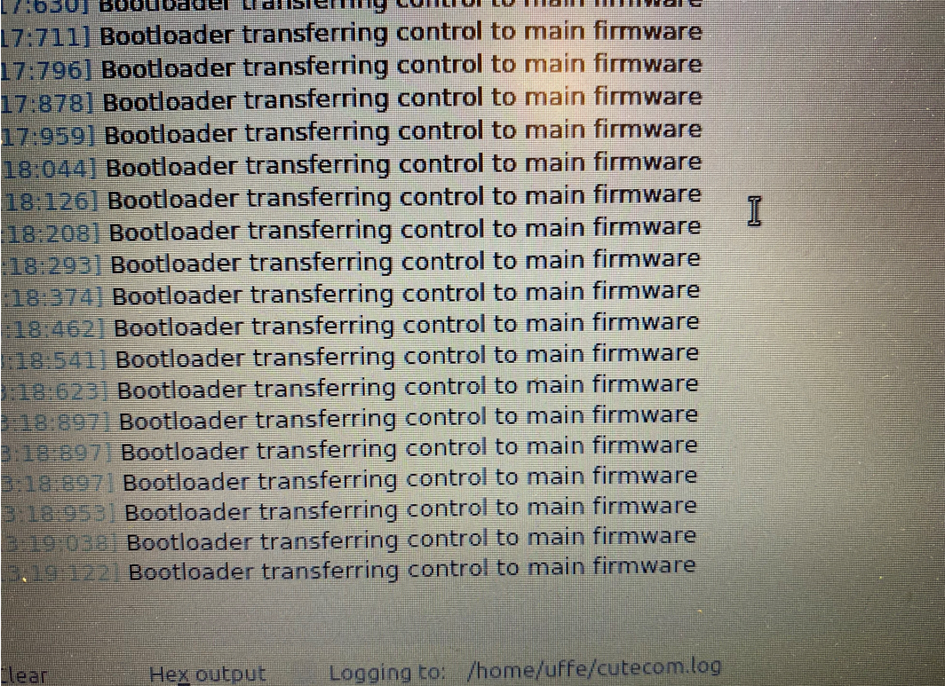
@dc42 I don't know for sure only assuming as the led is blinking very quickly and on the USB serial I get these:
EDIT: Sorry for the picture size.

It loaded an ran nicley when I had the step/dir configuration. I can also load the default sammy firmware without problems.
-
@dc42 Hi again,
I managed to find what caused it to crash.
Earlier I added this to get it to compile (src/Platform.cpp - void Platform::Spin() line# 982):
#if HAS_SMART_DRIVERS
# if !HAS_VOLTAGE_MONITOR                // <---- This
	SmartDrivers::Spin(true);        // <---- and this
# else                                   // <---- and this
	SmartDrivers::Spin(powered);
# endif                                  // <---- and finally this
Since powered doesn't exist if you have HAS_SMART_DRIVERS but not HAS_VOLTAGE_MONITOR.
If I change SmartDrivers::Spin(true) to SmartDrivers::Spin(false) it starts up but then I can't get the motors to run.

2022-01-29 22:33:40	m122 b124
Diagnostics for board 124:
Duet SAMMYC21 firmware version 3.4.0beta7+8 (2022-01-29 22:30:46)
Bootloader ID: not available
Never used RAM 432, free system stack 3888 words
Tasks: Move(notifyWait,0.0%,153) HEAT(notifyWait,0.1%,117) CanAsync(notifyWait,0.0%,64) CanRecv(notifyWait,0.0%,77) CanClock(notifyWait,0.0%,64) TMC(notifyWait,0.0%,71) MAIN(running,99.6%,445) IDLE(ready,0.0%,41) AIN(delaying,0.3%,166), total 100.0%
Last reset 00:00:31 ago, cause: power up
Last software reset time unknown, reason: HardFault, available RAM 432, slot 1
Software reset code 0x0060 ICSR 0x00000003 SP 0x20007f00 Task MAIN Freestk 6126 ok
Stack: 20001048 200036e4 ff003018 20003010 00000000 00017d25 00018a58 0100000f 00000000 20002f94 20001d70 a5a5a5a5 a5a5a5a5 a5a5a5a5 a5a5a5a5 00000000 00000013 000001f4 20001d44 00018337 00000000 000174a1 00000013 fffffffd 20002f88 00000000 00000002
Driver 0: pos 0, 160.0 steps/mm,ok, read errors 0, write errors 0, ifcnt 0, reads 0, writes 0, timeouts 0, DMA errors 0, CC errors 0, steps req 0 done 0
Driver 1: pos 0, 160.0 steps/mm,ok, read errors 0, write errors 0, ifcnt 0, reads 0, writes 0, timeouts 0, DMA errors 0, CC errors 0, steps req 0 done 0
Moves scheduled 0, completed 0, in progress 0, hiccups 0, step errors 0, maxPrep 0, maxOverdue 0, maxInc 0, mcErrs 0, gcmErrs 0
Peak sync jitter 0/10, peak Rx sync delay 194, resyncs 0/0, no step interrupt scheduled
MCU temperature: min 27.7C, current 27.9C, max 27.9C
Last sensors broadcast 0x00000000 found 0 118 ticks ago, 0 ordering errs, loop time 0
CAN messages queued 283, send timeouts 0, received 400, lost 0, free buffers 37, min 37, error reg 0
dup 0, oos 0/0/0/0, bm 0, wbm 0, rxMotionDelay 0
2022-01-29 22:50:59 m569 P124.1 Driver 124.1 runs forwards, active low enable, mode spreadCycle, ccr 0x00053, toff 3, tblank 0, hstart/hend/hdec 5/0/0, pos 0 2022-01-29 22:50:48 m569 P124.0 Driver 124.0 runs forwards, active low enable, mode spreadCycle, ccr 0x00053, toff 3, tblank 0, hstart/hend/hdec 5/0/0, pos 0 2022-01-29 22:54:40 M569.2 P124.1 R1 Error: M569.2: Failed to read register 2022-01-29 22:54:26 M569.2 P124.0 R0 Error: M569.2: Failed to read registerIf I do send powered = true to SmartDrivers::Spin I have to comment out tmcTask->Give() which I don't know what it does as I can't find it but it's probably something important.
void SmartDrivers::Spin(bool powered) noexcept { TaskCriticalSectionLocker lock; if (powered) { if (driversState == DriversState::noPower) { driversState = DriversState::notInitialised; //tmcTask->Give(); // wake up the TMC task because the drivers need to be initialised } } else if (driversState != DriversState::shutDown) { driversState = DriversState::noPower; // flag that there is no power to the drivers fastDigitalWriteHigh(GlobalTmc22xxEnablePin); // disable the drivers } } -
@gixxerfast you may need to increase the stack size of the TMC task. AFAIR the main board version of that file uses 150 words instead of 100.
-
@dc42 I increased the TMC task stack size to 150 words as you suggested but it behaves the same I'm afraid.
Is there any way I can prove, with gcode, that the UART communication with the TMC drivers is actually working?
The G569.2 P124.0 R1 fails to read the register which I can on the main board. Is that an indication of the UART communication not working or is it just because the driver isn't "awake" yet?
2022-01-30 11:37:48 M122 B124 Diagnostics for board 124: Duet SAMMYC21 firmware version 3.4.0beta7+8 (2022-01-30 11:33:54) Bootloader ID: not available Never used RAM 232, free system stack 3888 words Tasks: Move(notifyWait,0.0%,153) HEAT(notifyWait,0.1%,117) CanAsync(notifyWait,0.0%,64) CanRecv(notifyWait,0.0%,77) CanClock(notifyWait,0.0%,64) TMC(notifyWait,0.0%,121) MAIN(running,99.6%,445) IDLE(ready,0.0%,41) AIN(delaying,0.3%,154), total 100.0% Last reset 00:03:16 ago, cause: software Last software reset time unknown, reason: HardFault, available RAM 232, slot 2 Software reset code 0x0060 ICSR 0x00000003 SP 0x20007f00 Task MAIN Freestk 6126 ok Stack: 20001048 200036e4 ff003018 20003010 00000000 00017d25 00018a58 0100000f 00000000 20002f94 20001d70 20001544 a5a5a5a5 a5a5a5a5 a5a5a5a5 00000000 00000005 00000000 20001d44 00018337 00000000 000174a1 20001544 fffffffd 20002f88 00000000 00000002 Driver 0: pos 0, 80.0 steps/mm,ok, read errors 0, write errors 0, ifcnt 0, reads 0, writes 0, timeouts 0, DMA errors 0, CC errors 0, steps req 0 done 0 Driver 1: pos 0, 80.0 steps/mm,ok, read errors 0, write errors 0, ifcnt 0, reads 0, writes 0, timeouts 0, DMA errors 0, CC errors 0, steps req 0 done 0 Moves scheduled 0, completed 0, in progress 0, hiccups 0, step errors 0, maxPrep 0, maxOverdue 0, maxInc 0, mcErrs 0, gcmErrs 0 Peak sync jitter 1/12, peak Rx sync delay 195, resyncs 0/0, no step interrupt scheduled MCU temperature: min 24.5C, current 25.4C, max 25.5C Last sensors broadcast 0x00000000 found 0 62 ticks ago, 0 ordering errs, loop time 0 CAN messages queued 1596, send timeouts 0, received 2558, lost 0, free buffers 37, min 37, error reg 0 dup 0, oos 0/0/0/0, bm 0, wbm 0, rxMotionDelay 0 -
@gixxerfast we can probably use the hard fault data to debug this. First we need to be sure that this hard fault data related to this problem. So with working firmware on the Sammy, send M122 B124 P1005 (assuming the board address is still 124). This should reset the Sammy and M122 should then display the last reset reason as "Deliberate hard fault". If that works, put the problem firmware on the board and let it boot up and reset a couple of times. Then put the working firmware on the board and run M122 again. If the work "Deliberate" is no longer in the reset data, then the hard fault data refers to the recent reset, and we can take it form there. In the first instance I will need the reset data and also the .map file from the build of the failing firmware.
-
PS - the "Never used RAM" value looks very low to me. Have you added any features other than the two TMC2209 drivers to your build?
-
@dc42 No, not that I'm aware of. Think I removed most of it.
// General features #define HAS_VREF_MONITOR 0 #define HAS_VOLTAGE_MONITOR 0 #define HAS_12V_MONITOR 0 #define HAS_CPU_TEMP_SENSOR 1 #define HAS_ADDRESS_SWITCHES 0 #define HAS_BUTTONS 1 // I don't have a button. // Drivers configuration #define SUPPORT_DRIVERS 1 #define HAS_SMART_DRIVERS 1 #define HAS_STALL_DETECT 0 #define SINGLE_DRIVER 0 #define SUPPORT_SLOW_DRIVERS 0 #define SUPPORT_DELTA_MOVEMENT 0 #define USE_EVEN_STEPS 0 #define ACTIVE_HIGH_STEP 1 // 1 = active high, 0 = active low #define ACTIVE_HIGH_DIR 0 // 1 = active high, 0 = active low #define SUPPORT_TMC51xx 0 #define SUPPORT_TMC2160 0 #define SUPPORT_TMC2660 0 #define SUPPORT_TMC22xx 1 #define TMC22xx_USES_SERCOM 1 #define TMC22xx_HAS_MUX 0 #define TMC22xx_SINGLE_DRIVER 0 #define TMC22xx_HAS_ENABLE_PINS 0 #define TMC22xx_VARIABLE_NUM_DRIVERS 0 #define TMC22xx_USE_SLAVEADDR 1 #define TMC22xx_DEFAULT_STEALTHCHOP 0 #define SUPPORT_THERMISTORS 0 #define SUPPORT_SPI_SENSORS 0 #define SUPPORT_I2C_SENSORS 0 #define SUPPORT_LIS3DH 0 #define SUPPORT_DHT_SENSOR 0 #define SUPPORT_SDADC 0 #define USE_MPU 0 #define USE_CACHE 0 -
@dc42 OK, let's see if this went OK.
Before with the induced fault:
Last reset 00:00:13 ago, cause: software
Last software reset at 2022-01-30 12:28, reason: deliberate HardFault, available RAM 232, slot 0
Software reset code 0x8060 ICSR 0x00000003 SP 0x20002b20 Task MAIN Freestk 758 ok
Stack: 20000001 00000000 00020104 00000001 00000000 00011491 00011fa8 01000000 00000000 4e49414d 20000f48 00000000 20001048 200036e4 ff003018 20003010 00000000 00017d25 00000000 00000000 a5a5a5a5 20002c08 200014ec 00000005 a5a5a5a5 20002c08 00000001
Then after with the "real" fault:
Last reset 00:00:44 ago, cause: software
Last software reset time unknown, reason: HardFault, available RAM 232, slot 1
Software reset code 0x0060 ICSR 0x00000003 SP 0x20007f00 Task MAIN Freestk 6126 ok
Stack: 20001048 200036e4 ff003018 20003010 00000000 00017d25 00018a58 0100000f 00000000 20002f94 20001d70 20001544 a5a5a5a5 a5a5a5a5 a5a5a5a5 00000000 00000005 00000000 20001d44 00018337 00000000 000174a1 20001544 fffffffd 20002f88 00000000 00000002
And the map file:
Duet3Firmware_SAMMYC21.map.stpPlease note that I had to change the file name extension to cheat the forum software.
I hope I executed this correctly.
-
@gixxerfast thanks. I think the main task stack may be overflowing, because the reported main task stack of 6126 is greater than the allocated amount. Try increasing it in line 54 of file Tasks.cpp. I suggest you increase it from 850 to 900. However, as you have so little RAM left you will have to reduce the TMC task stack size back to 100.
-
@dc42 Hi and thanks for the answer.
It did not remove the problem though. However I found this and I changed a bit and now it doesn't crash but then again I don't have any drivers after this it seems.
bool DoTransaction(size_t driverNumber)
{
	TmcDriverState *currentDriver;
#if TMC22xx_SINGLE_DRIVER
	currentDriver = driverStates;
//#elif TMC22xx_USE_SLAVEADDR //UER
//	const size_t mappedDriverNumber = ((driverNumber & 1u) << 2) | (driverNumber >> 1);	// this assumes we have between 5 and 8 drivers
//	currentDriver = &driverStates[mappedDriverNumber];
#else
	currentDriver = &driverStates[driverNumber];
#endif
It's the comment "// this assumes we have between 5 and 8 drivers" that makes me wonder.
Now, I don't know if the Samc is bigendian/littleendian but when I try that on the X86/Linux with G++ it looks a bit strange to me.

2022-01-30 14:53:23 M122 B124 Diagnostics for board 124: Duet SAMMYC21 firmware version 3.4.0beta7+8 (2022-01-30 14:06:17) Bootloader ID: not available Never used RAM 224, free system stack 3888 words Tasks: Move(notifyWait,0.0%,153) HEAT(notifyWait,0.0%,117) CanAsync(notifyWait,0.0%,64) CanRecv(notifyWait,0.0%,77) CanClock(notifyWait,0.0%,64) TMC(notifyWait,0.5%,61) MAIN(running,99.2%,470) IDLE(ready,0.0%,41) AIN(delaying,0.3%,154), total 100.0% Last reset 00:45:33 ago, cause: software Last software reset time unknown, reason: HardFault, available RAM 224, slot 2 Software reset code 0x0060 ICSR 0x00000003 SP 0x20007f00 Task MAIN Freestk 6126 ok Stack: 20001048 200037b4 ff0030e8 200030e0 00000000 00017cf5 00018a28 0100000f 00000000 20003064 20001d70 a5a5a5a5 a5a5a5a5 a5a5a5a5 a5a5a5a5 00000000 20001d40 00000000 a5a5a5a5 00018307 00000000 00017471 00000000 fffffffd 20003058 00000000 00000002 Driver 0: pos 0, 160.0 steps/mm,not present, steps req 0 done 0 Driver 1: pos 0, 160.0 steps/mm,not present, steps req 0 done 0 Moves scheduled 0, completed 0, in progress 0, hiccups 0, step errors 0, maxPrep 0, maxOverdue 0, maxInc 0, mcErrs 0, gcmErrs 0 Peak sync jitter -1/14, peak Rx sync delay 199, resyncs 0/0, no step interrupt scheduled MCU temperature: min 26.9C, current 28.9C, max 29.0C Last sensors broadcast 0x00000000 found 0 155 ticks ago, 0 ordering errs, loop time 0 CAN messages queued 21718, send timeouts 0, received 35251, lost 0, free buffers 37, min 37, error reg 0 dup 0, oos 0/0/0/0, bm 0, wbm 0, rxMotionDelay 0 -
@gixxerfast line 1606/1607 should be changed to:
#elif TMC22xx_USE_SLAVEADDR && TMC22xx_HAS_MUX
	const size_t mappedDriverNumber = ((driverNumber & 1u) << 2) | (driverNumber >> 1);	// this assumes we have between 5 and 8 drivers and a 2-way multiplexer
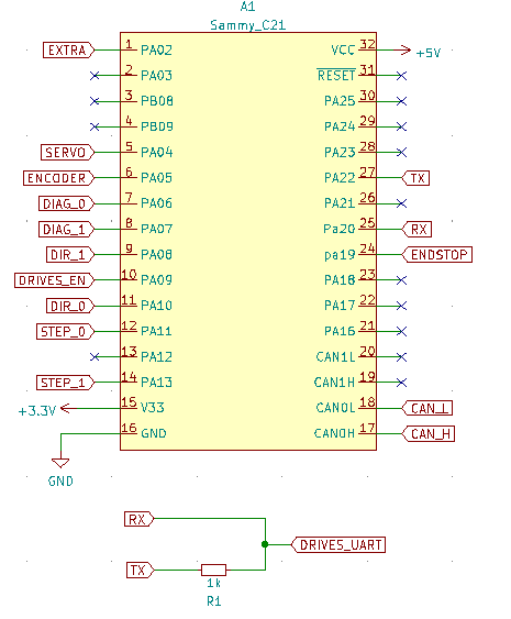
The fact that is now reporting the drivers are "not present" indicates that it is trying to talk to them. How did you connect the drivers to the sercom transmit and receive pins on the sammy?
-
PS - lines 1482-1484 are currently:
#if TMC22xx_HAS_MUX
	SetUartMux();
#endif
I think you may need instead:
#if TMC22xx_HAS_MUX SetUartMux(); #elif TMC22xx_USE_SLAVEADDR delay(2); // give the previous TMC22xx driver time to get off the bus #endif -
constexpr uint8_t TMC22xxSercomNumber = 3;
Sercom * const SERCOM_TMC22xx = SERCOM3;

constexpr Pin TMC22xxSercomTxPin = PortAPin(22);
constexpr GpioPinFunction TMC22xxSercomTxPinPeriphMode = GpioPinFunction::C;
constexpr Pin TMC22xxSercomRxPin = PortAPin(20);
constexpr GpioPinFunction TMC22xxSercomRxPinPeriphMode = GpioPinFunction::D;
constexpr uint8_t TMC22xxSercomRxPad = 2;
constexpr IRQn TMC22xxSercomIRQn = SERCOM3_IRQn;

I really hope I haven't messed up here.
Also, earlier I had to change this one too:
inline void TmcDriverState::UartTmcHandler() noexcept { -#if !(TMC22xx_HAS_MUX || TMC22xx_SINGLE_DRIVER) +#if !(TMC22xx_HAS_MUX || TMC22xx_SINGLE_DRIVER || TMC22xx_USE_SLAVEADDR) # if TMC22xx_USES_SERCOM DmacManager::DisableCompletedInterrupt(TmcRxDmaChannel); # else -
@gixxerfast yes that change to UartTmcHandler is correct.
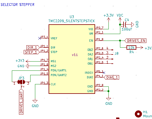
The stepsticks need to be wired such that DRIVES_UART is routed to pin 14 of the TMC2209 chip as it is on the tool board. The MS1 and MS2 pins of the chip need to be both grounded for driver 0, whereas for driver 1, MS1 should be connected to +3.3V and MS2 grounded as you have illustrated.
Did you see my message about the SetUartMux call?
-
@dc42 said in Sammy C21 support for 2 TMC2209 drivers with UART com:
Did you see my message about the SetUartMux call?
Yes, if you mean this I have added that:
#if TMC22xx_HAS_MUX
	SetUartMux();
#elif TMC22xx_USE_SLAVEADDR
	delay(2);							// give the previous TMC22xx driver time to get off the bus
#endif
OK, I'll check the pin on the TMC2209 chip, but I think it should be alright.
EDIT: Yes, DRIVES_UART (via PDN_UART) is connected to pin 14 on the TMC2209 chip.On the first step stick both MS1 and MS2 are connected to ground.
-
@gixxerfast lines 569 and 626 should also have || TMC22xx_USE_SLAVEADDR appended.
-
@dc42 OK thanks, done. Behaviour unchanged though.
-
@gixxerfast have you disabled I2C support in your SAMMYC21.h file? That also uses SERCOM3.