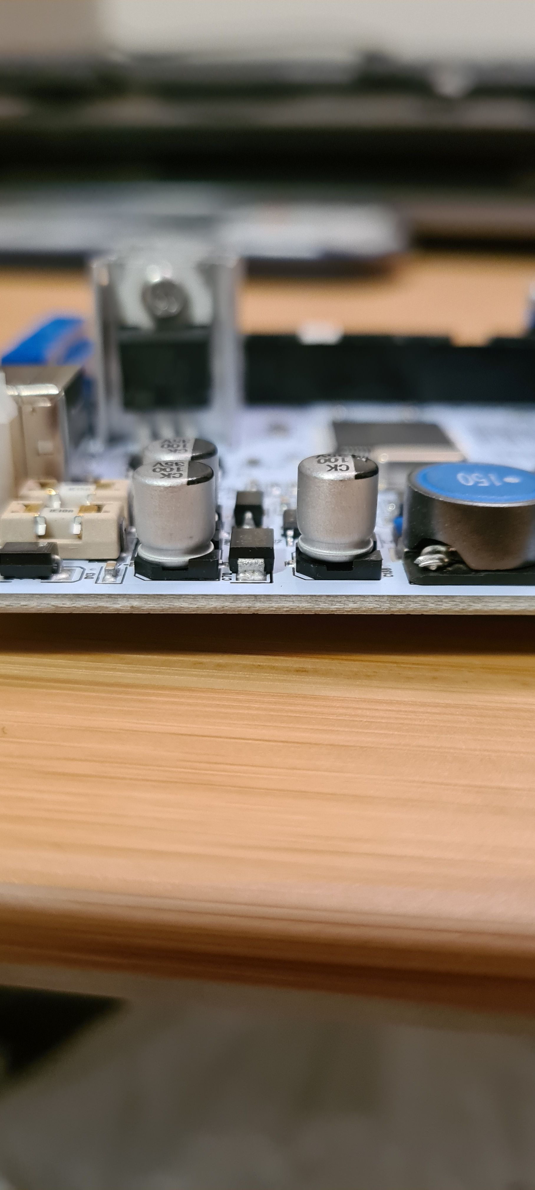
Help understanding a (non Duet) board failure
-
Hello
 First off, this is a non-Duet & non-RRF board, but I am hoping someone can help impart some electronics wisdom to help me understand a failure I have seen on one of my printers. I believe it may have been a random component failure, but would like to understand if there is something I am missing
The failure - I believe it is a smoothing capacitor (C138 on the schematic) that has popped. It's the electrolytic capacitor on the right in this photo - it should be the same as the others, but is now 2mm taller (and is short circuited). It ties the 12V line (after fuses) to ground just before the 5V converter. My presumption is that this is just a low-pass filter to stop things disturbing the 5V regulator (I may be wrong here...). Having removed the capacitor and replaced the blown fuse, the board now works again (i.e. with C138 missing).

Relevant part of the schematic:

(full schematic is here if interested: https://www.geeetech.com/wiki/images/d/d3/Hardware_GT2560_RevA%2B.pdf)The failure happened towards the end of a PID tune of the hotend. I smelled something burning mid way though tuning but assumed it was just the 'new hotend smell' (I had just put a new hotend on the printer, though it wasn't the first time heating it up). However, after the PID finished and the hotend cooled, the smell got worse and the fuse blew - dead board. No other components appear to be affected as the board now works with the blown capacitor removed.
I didn't see any way you could over-cook that capacitor unless there was some very high voltage, or a lot of high-frequency load on it, but I don't see any way that could happen...? The board has been used for a while prior to this, though I had just upgraded the hotend and added a mini IR probe (which I belive may just be coincidence...).
Am I missing something? And does anyone have a view on how critical that capacitor might be, given the board works without it (though I haven't stress tested yet...)?
For info, it's a Geetech GT2560A+ on an i3 clone running marlin. Worst case scenario is the board does go pop in some other way and i'm 'forced' to get another Duet

-
@engikeneer they should have used a ceramic capacitor in that position, or a ceramic capacitor in parallel with an electrolytic. That capacitor carries the input ripple current of the regulator, so it's important to use a capacitor with a low ESR at the switching frequency (360kHz). It will likely have failed because of local overheating.
-
@dc42 thanks for the explanation - I'll see what replacements I can find
-
 undefined engikeneer marked this topic as a question
-
 undefined engikeneer has marked this topic as solved
-
@engikeneer you can get 10uF 50V ceramic capacitors in case size 2220. You could check whether that case size will fit in the same space as the ex-electrolytic.
-
@dc42 Much appreciated once again! 2220 would fit in the space but wouldn't be a pretty soldering job with how the pads are laid out. I've opted for some through-hole 10uF 50V ceramic ones to try first and will see how I go.