Accelerometer Usage
-
@phaedrux said in Accelerometer Usage:
@ccs86 said in Accelerometer Usage:
@phaedrux said in Accelerometer Usage:
@ccs86 Are you using a Maestro board?
Yes.
The lack of floating point unit makes accelerometer usage problematic. I didn't even think there was a build for the Maestro.
It is my understanding that accelerometer usage is okay, with the potential issue being in running input shaper. I'd still like to start measuring with the accelerometer for a baseline and for mechanically trying to improve resonance.
@dc42 Can confirm if that is the case.
-
@ccs86 confirmed. Accelerometers should work with the Maestro, but I haven't tested that combination.
-
@ccs86 I'm using a CAT7 cable but it not working...I don't know how to fix the problem.
-
@ducati87 I plan to test accelerometer support on the Maestro next week.
-
@dc42 hey so i got now everything working on my board. Also using now the resistor. But now what should i do with the data? How can i now use input shaper? I mean i can view it an hit analyze, but then? Not sure what i should do next.
-
@ducati87 I can confirm that accelerometer support does work on the Maestro. I have update https://duet3d.dozuki.com/Wiki/Accelerometers to include a photo showing the wiring I used. The ribbon cable is 1m long.
I also successfully ran an accelerometer using exp.pa21 and exp.pa22 for the CS and INT signals instead of TWD0 and TWCK0.
-
@dc42 can an accelerometer be connected to a 3HC?
-
@jay_s_uk said in Accelerometer Usage:
@dc42 can an accelerometer be connected to a 3HC?
Not yet, but I will probably add support for that at some point.
-
@dc42 ok thanks. Would be helpful as I currently run all my tools off a 3HC and that's where all my wiring goes back to. Its also on the opposite side of my printer to the 6HC.
-
@dc42 said in Accelerometer Usage:
@ducati87 I can confirm that accelerometer support does work on the Maestro. I have update https://duet3d.dozuki.com/Wiki/Accelerometers to include a photo showing the wiring I used. The ribbon cable is 1m long.
I also successfully ran an accelerometer using exp.pa21 and exp.pa22 for the CS and INT signals instead of TWD0 and TWCK0.
Any ideas on what to try next?
I am running:
- CAT6 cable, less than 1m length.
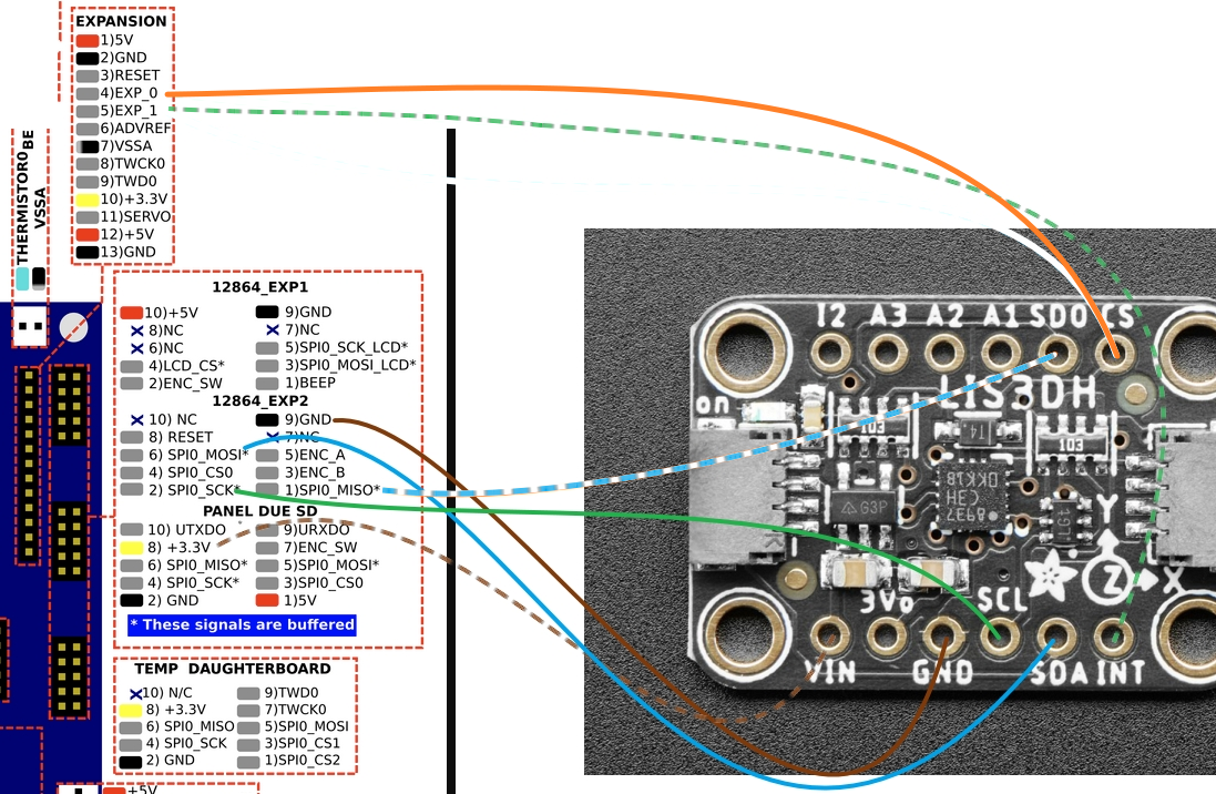
- CS is run on a conductor with an unused pair (CS on orange, nothing on orange/wht)
- 1k resistor on SDO
- CS >>> EXP_0
- INT >>> EXP_1
- M955 P0 C"exp.pa21+exp.pa22"
Not found....

-
@ccs86 try using the temp daughterboard connector instead of the 12864_EXP2 connector. If you have a temperature daughterboard installed, you can connect to the pins on top of it.
-
@dc42 said in Accelerometer Usage:
@ccs86 try using the temp daughterboard connector instead of the 12864_EXP2 connector. If you have a temperature daughterboard installed, you can connect to the pins on top of it.
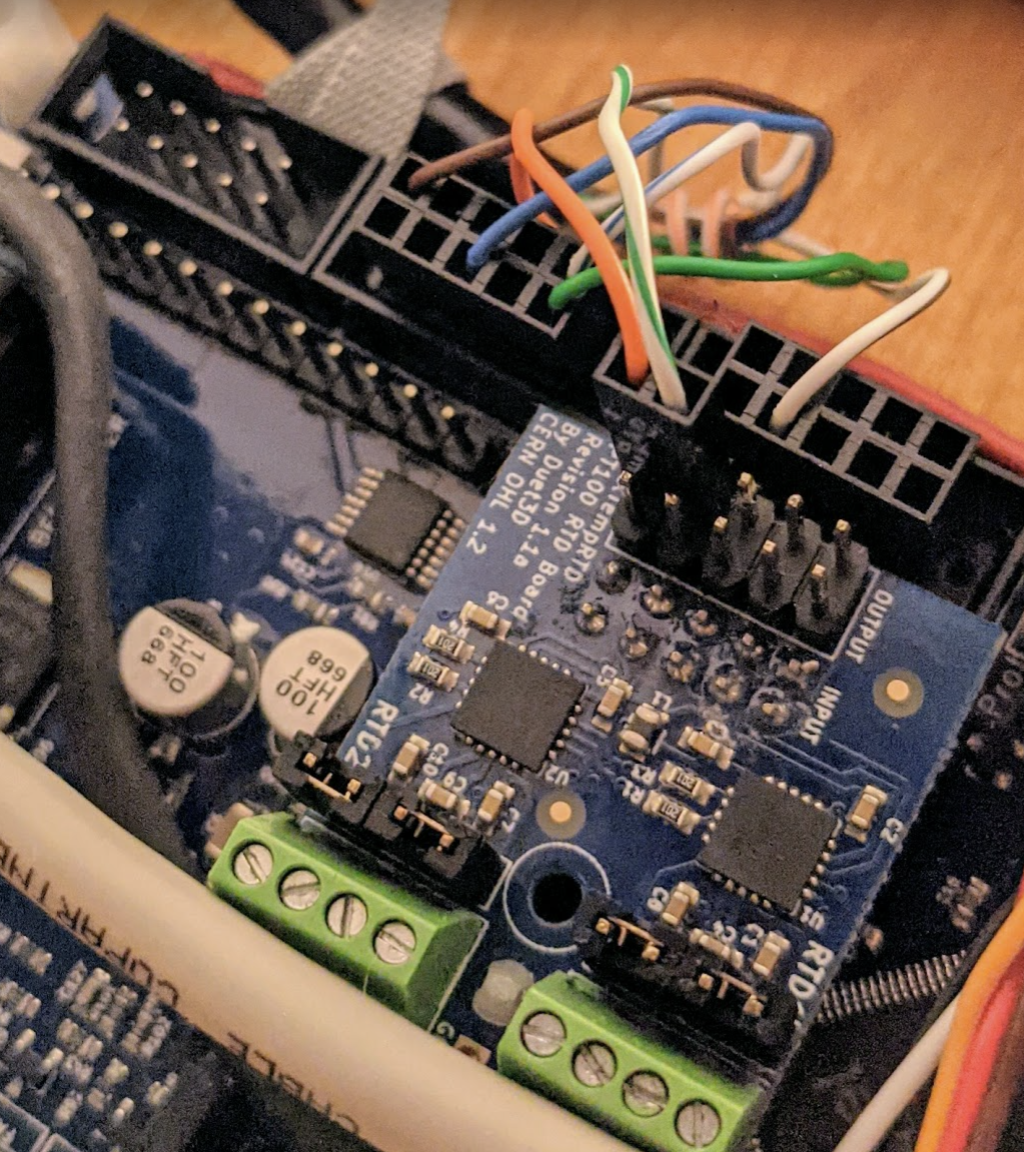
I just tried like this and still get the not found error:
M955 P0 C"twd0+twck0"
(I assume that is a typo in your dozuki edit: Unknown pin name 'twcl0')
(orange is CS... wht/grn is INT)

-
@ccs86
do you have evidence that the accelerator board is OK? -
@o_lampe said in Accelerometer Usage:
@ccs86
do you have evidence that the accelerator board is OK?The green light comes on, so that's a start. I'm not sure what else I might be able to test with my multimeter.
-
@ccs86 said in Accelerometer Usage:
@dc42 said in Accelerometer Usage:
@ccs86 try using the temp daughterboard connector instead of the 12864_EXP2 connector. If you have a temperature daughterboard installed, you can connect to the pins on top of it.
I just tried like this and still get the not found error:
M955 P0 C"twd0+twck0"
(I assume that is a typo in your dozuki edit: Unknown pin name 'twcl0')
(orange is CS... wht/grn is INT)

@dc42 Does this setup look correct? Any other ideas?
-
@ccs86 said in Accelerometer Usage:
Does this setup look correct? Any other ideas?
No, it isn't correct. If the PT100 board was not there, it might be correct. However, the PT100 board does not route TWD0 and TWCK0 straight through, it routes them to the CS2 and CS1 positions on the top connector, so that if you stack another daughterboard on top, it will use TWCK0 and TWD0 instead of CS1 and CS2.
-
@dc42 said in Accelerometer Usage:
@ccs86 said in Accelerometer Usage:
Does this setup look correct? Any other ideas?
No, it isn't correct. If the PT100 board was not there, it might be correct. However, the PT100 board does not route TWD0 and TWCK0 straight through, it routes them to the CS2 and CS1 positions on the top connector, so that if you stack another daughterboard on top, it will use TWCK0 and TWD0 instead of CS1 and CS2.
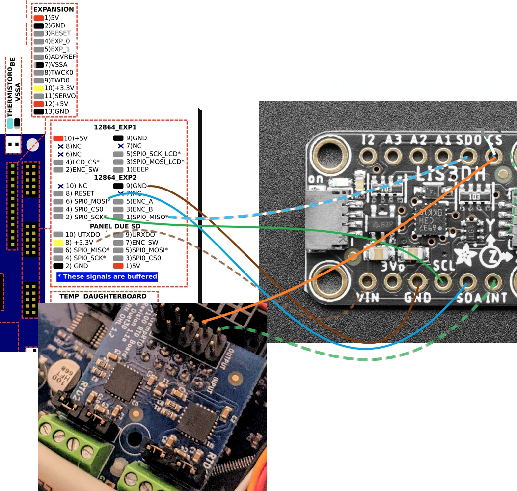
Like this then?
M955 P0 C"twd0+twck0"

-
@ccs86 that looks better. Alternatively, connect all the accelerometer wires to the connector on top of the PT100 board.
Edit: I think you may have the orange and dashed green wires crossed.
I can test that configuration when my bench system is free again.
-
@dc42 said in Accelerometer Usage:
@ccs86 that looks better. Alternatively, connect all the accelerometer wires to the connector on top of the PT100 board.
Edit: I think you may have the orange and dashed green wires crossed.
I can test that configuration when my bench system is free again.
Do you have a complete pinout for the installed daughterboard? I wasn't able to find one on the wiki.
When you say "crossed", do you just mean mis-matched to the M955 P0 C"twd0+twck0"?
So I could physically swap the wires, or update to M955 P0 C"twck0+twd0"?
-
@ccs86 said in Accelerometer Usage:
So I could physically swap the wires, or update to M955 P0 C"twck0+twd0"?
yes.