Multitool identification
-
I hope you can give me ideas on how to do this on our 3-head printer:
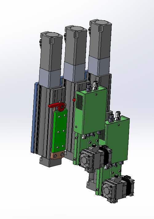
The printer has 3 independent Z axes on a carriage on the X axis, each of the Z has a tool holder. There are currently 6 types of possible heads that can go indistinctly in any position of the 3 tool holders (manual change). Each tool is driven by a 1LC plate, which controls its extruder, temperature, fan, offsets, etc. Base board is a 6HD and 1XD for each servo axis(closed loop).
Each 1LC board has its individual CAN address configured.In this example, carriage loaded with 2 Hemera tools in 2 and 3 positions:

How can I tell the printer which head is present and in which Z position it is located? The idea is to configure all the 1LC boards sequentially and that the identification is by their CAN number? What if a CAN address is configured but not present?
How could a user easily indicate the tool, without touching the configuration files?
Ideas are welcomed.
-
To identify which tool is in which position, I suggest you use microswitches to distinguish between them. One option is to put 2 microswitches or optical proximity sensors (e.g. ITR20001/T or TCRT1000) on each tool, connected to the tool board IOx_IN ports. Then arrange that each of the three tool positions has indentations or bumps that activate the microswitches/sensors or not in different ways for each position. For example, one position could activate just the first switch, the next position just the second switch, and the third position both switches. A tool that was connected but not docked in any position would have neither switch activated.
To determine which tools are loaded, in config.g you can have a G4 delay command to give the tool boards time to start up or reset, the you can query the object model 'boards' array to see which CAN addresses are present. For each present CAN address that corresponds to a tool board, you can then configure input port on it to ask it which microswitches are activated, to establish the position of that tool.
-
@dc42 Sounds good!
Do you have a config.g example where these boards array could be inspected?
We thought a macro function or a button in DWC to indicate which printhead and where it is located.
But of course your automated option is superior in terms of usability.
We will try to explore the possibility of integrating this sensorization into the heads. The physical part at least doesn't seem complicated. -
Along similar lines to what DC42 has suggested, if you have to electrically connect each "tool" you can use a plug with additional pins and allocate each to an gpio pin on the board
We do this sometimes with welding jigs on robots.
When you plug in the jig, the robot just checks which io is closed the runs the associated welding program. -
The tool count on Duets can go up to ~50 tools.
Assuming this will be tried out eventually, I thought of a 'QR code for the Blind' sensor field.
Envision a QR code-like square pattern (3x3 would do), but with Dots and dents (*). The sensor field would then read the Dots as '1' and the dents as '0'. It could have SPI or CAN, which would be better than connecting 8 datalines to GPIO pins.
*) could be north- and southpole magnets on a Hallsensor array, too.It's only a vision, but sometimes they come true.
-
@marcossf said in Multitool identification:
@dc42 Sounds good!
Do you have a config.g example where these boards array could be inspected?
We thought a macro function or a button in DWC to indicate which printhead and where it is located.
But of course your automated option is superior in terms of usability.
We will try to explore the possibility of integrating this sensorization into the heads. The physical part at least doesn't seem complicated.I don't have a config.g that does this, however this macro to list connected expansion boards may get you started:
while iterations < #boards if iterations != 0 ; skip the main board echo "Expansion board type",boards[iterations].shortName,"found at CAN address",boards[iterations].canAddress -
@o_lampe @OwenD Thank you very much for your input.
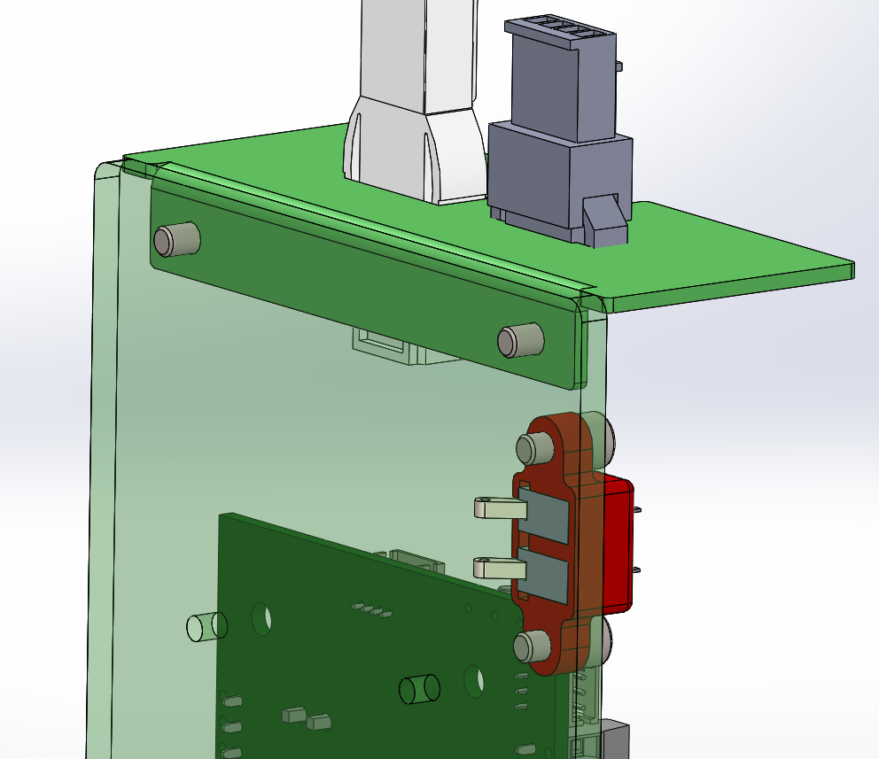
I think the first thing we will try will be with a couple of mechanical submicro switches (Omron D3C-1210) housed inside printhead connected to the 1LC board. It seems the simplest solution.

With this, we will have the position of the printhead (values 11, 01, 10, 00) sufficient to know where it is. We have yet to see how to relate the CAN position and this physical position, but I understand that it's a software issue that we will have to find out.
-
@dc42 said in Multitool identification:
@marcossf said in Multitool identification:
@dc42 Sounds good!
Do you have a config.g example where these boards array could be inspected?
We thought a macro function or a button in DWC to indicate which printhead and where it is located.
But of course your automated option is superior in terms of usability.
We will try to explore the possibility of integrating this sensorization into the heads. The physical part at least doesn't seem complicated.I don't have a config.g that does this, however this macro to list connected expansion boards may get you started:
while iterations < #boards
  if iterations != 0  ; skip the main board
    echo "Expansion board type",boards[iterations].shortName,"found at CAN address",boards[iterations].canAddress
OK, we will try that. I'm pretty sure that my request for help will not end here.
