Logic Level shifter for 12864 display on Duet 2 Wifi
-
for what its worth i had no issues on the Maestro, beyond the polarity on the geeetech display headers being wrong and the encoder skipping two entries which was solved by
E2inM918as such I didn't bother testing on the Wifi board.I'm guessing dc42 wil be done with his 756x stuff by the time I get the cast* off and will poke it some more then
*) give the kids alcohol before the sports get them!
-
@oliof Thanks! Yesterday came to the same conclusion as you did the same, initializing twice and it works. About the button I dig in some Arduino forums and tested the encoder, when I press it closes a circuit to ground so the hardware is fine. In my case, the rotary works just fine is only the switch button.
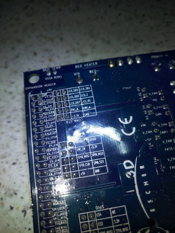
When I donwloaded @bearer's patch, in it is clearly defined that the pin used for the encoder switch is number 8 and that it connects to CONN_LCD 10.+// 12864 LCD
+// The ST7920 datasheet specifies minimum clock cycle time 400ns @ Vdd=4.5V, min. clock width 200ns high and 20ns low.
+// This assumes that the Vih specification is met, which is 0.7 * Vcc = 3.5V @ Vcc=5V
+// The Duet Maestro level shifts all 3 LCD signals to 5V, so we meet the Vih specification and can reliably run at 2MHz.
+// For other electronics, there are reports that operation with 3.3V LCD signals may work if you reduce the clock frequency.
+// ST7920 doesn't allow SCK/MISO signals when CS is not asserted, therefore the AND gate on the Maestro
+constexpr uint32_t LcdSpiClockFrequency = 2000000; // 2.0MHz -- Top View --
+constexpr Pin LcdCSPin = 7; //connsd.7 --> gate -> exp1.4
+constexpr Pin LcdBeepPin = 60; //connlcd.4 -> exp1.1
+constexpr Pin EncoderPinA = 85; //connlcd.8 -> exp2.5
+constexpr Pin EncoderPinB = 25; //connlcd.6 -> exp2.3
+constexpr Pin EncoderPinSw = 8; //connlcd.10 -> exp1.2Seeing other diagrams in this post and also Schenk's tried out to connect the ENC_SW to the original CONN_SD.7 and it worked! But now I had an important issue, the 3.3v that should go to the LCD_CS were in an open circuit, but, nevertheless the LCD worked, maybe my model was one of the ones that can operate with 3.3 v signals. Now, since LCD_CS was always on 3.3 v, and it needed to be for the AND gates to work, I connected it directly to a 3.3 v of the expansion and now the display starts just fine and have even taken the delay in the config.g. I assume that on power up, the M918 preceeds the initialization sequence in the Duet and therefore we had to make a delay in order of it to work. I bet that if you take the first M918 and just use a delay of 2 seconds it will work just fine.
So, my wiring is as of @bearer's patch and schematics but connecting EXP1.1 to CONN_SD.7 and the SN74HCT08DR 2A or pin4 to a 3.3 v source.
Now I have to test the SD card, need to find another one and see if I can read it.
-
@bearer I solved, not in a fancy way but it works. Many thanks!
-
Not sure I quite followed you there, but sounds like the rrf3 binary may have been built before i swapped the two pins
-
@bearer I think so and it makes sense since the patch says v2.05. The funny thing is that when I uploaded v2.05 the encoder switch didn't work also, maybe was bad wiring from my part, since I'm on a breadboard.
Just tested the SD card and works perfect, remembered I had another in an old phone.
I will solder now and make the wires. Again, many thanks guys. @bearer or @oliof if in the future you want my schematic (the change I made from @bearer's) I'll post it.
-
Please post what you have (-;
-
@oliof Sorry for taking so long to reply. Couldn't make some time until today to return to this personal project. The change I made from @bearer schematic is ENC_SW and LCD_CS pins, below the image with the changes. I think this could only work for @bearer's RRF3 https://www.dropbox.com/s/f7fjuu7f0wcf7dc/Duet2CombinedFirmware-rrf3-lcd.bin?dl=1.
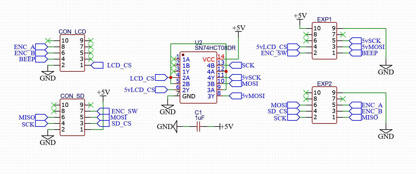
The only issue I find is that when accesing the SD card on the LCD12864 some lines appear on the display and have to clean them by manually entering M918 P1, even make a macro to just run it.
I'll be looking regurlarly at this posts in case anyone needs help or when @dc42 uploads his 3.2 version. See you guys around and again many thanks to everyone! -
If you get artifacts when accessing the SD card slot, it's likely noise on the SPI connection. Try shielded it at least twisted cables.
-
@oliof OK, thanks for the tip! Surely is that now that you mention it. I did the circuit soldering wire graps and the rest is ribbon cable unshielded.
-
Tested 12864 fysetc mini in beta 3.2.2 duetwifi and dont work @dc42 connected as you sugested in previous post, M122 dont report error.
Try P1 and P2 with M918 and dont work.
-
@seraser said in Logic Level shifter for 12864 display on Duet 2 Wifi:
Tested 12864 fysetc mini in beta 3.2.2 duetwifi and dont work @dc42 connected as you sugested in previous post, M122 dont report error.
Try P1 and P2 with M918 and dont work.
Please post your exact config line for the M918 command.
- I'm not sure of the Duet Wifi situation and what display support it currently includes. Did you build the firmware yourself?
- P2 is definitely the display type you want.
- If you are sure of the electrical connections, logical levels and voltage levels, then trying R6 for the resistor ratio and playing around with the C parameter (contrast 0-100) could work.
- Perhaps starting with a slow SPI frequency (F parameter) also helps.
So something like
M918 P2 R6 C60 F200000may just work. -
@Schmart thank you for your response.
Changelog of 3.2 beta 2 says:
Supports ST7567-based 12864 displays on Duet Maestro and Duet WiFi (thanks to SchmartMaker for writing the ST7567 driver code)
So Im testing with 2.1 and 1.2 versión of fysetc mini 12864 with the pin asignement by @dc42, exp1 of mini to LCD exp in duet and exp2 mini to sd exp of duet, direct conection.
But something is not good, not work with your M918 line and if I rotate the encoder duet restart, maybe shorcut, with two LCDs.
-
If the encoder turning causes a reset, the wires might be turned 180 degrees.
-
@oliof I used dc42 pin asignement.
-
@oliof said in Logic Level shifter for 12864 display on Duet 2 Wifi:
If the encoder turning causes a reset, the wires might be turned 180 degrees.
Oliof might be right. Just to rule out a wiring problem, can you provide a photo of the connections you made between the display and the mainboard so we can check?
You may have done so already, but for troubleshooting purposes, I would also suggest to only connect the wires that are absolutely necessary for a working display.
Just checked the source code and the pin mapping that David mentioned hasn't changed. You compiled the firmware yourself with
#define SUPPORT_12864_LCD?The only change made to the source code recently was to the default contrast (changed to C30) for a ST7565 display. I believe David has used the Fysetc Mini12864 display to test the code with, so the default settings for the P2 display type should be already optimized for that model.
-
@Schmart Firmware is 3.2beta2, public, not compiled for me.
Wiring is simple, exp1 of lcd to explcd on duet and exp2 of lcd to expsd on duet, checked pin asignement but maybe I miss some thing.
With fysetc mini v1.2 backlight and leds light but with fysetc v2.1 nothing light and with both displays rotate the encoder result restart.
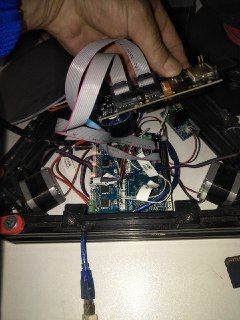
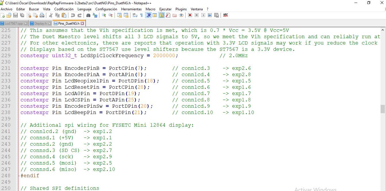
From github sources:
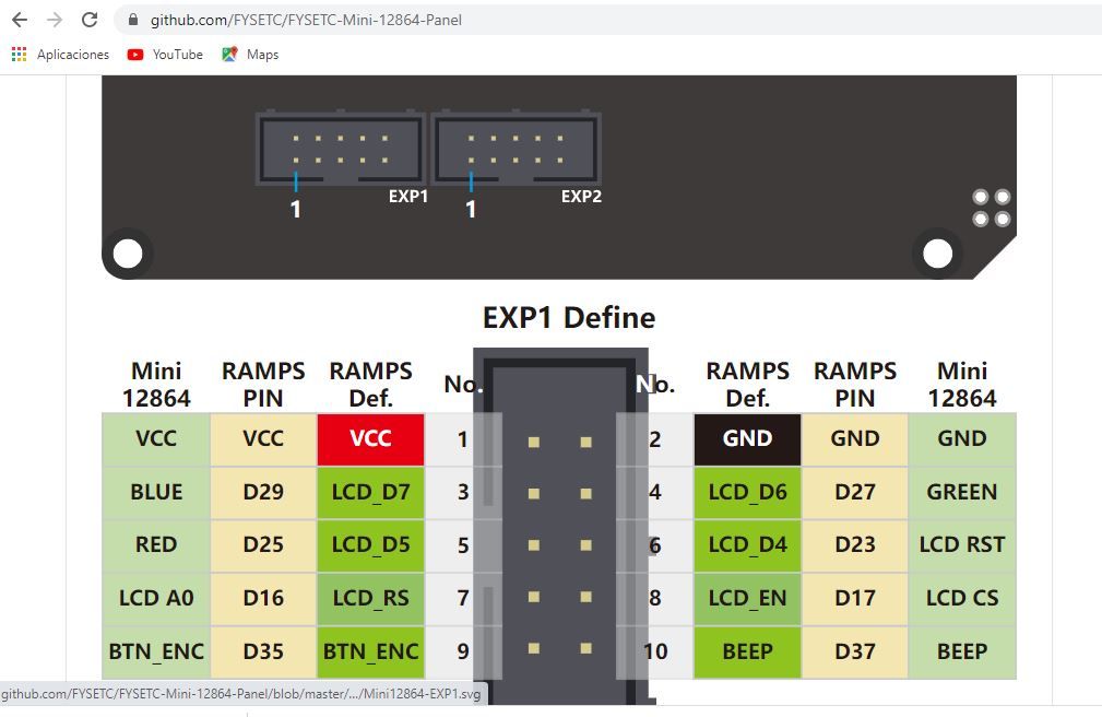
Pinout fysetc:
Edit:
My bad, checked under board pinout and my wiring is bad for bad initial comprension, I will redo the wiring with board pinout, sorry my bad english Im spanish.
-
-
@Schmart doesn't work, conected from connlcd2 to connlcd10 and supply 5v and only light with 1.2 version and no lights with 2.1 version tested with many M918 P2 configs.
I will test both LCD with ramps and if work ok I will stop because best choice is wait other guy trying.
Best regards.
-
The version 2.1 Fysetc display won't work on the Duet WiFi (yet) because RRF for Duet 2 doesn't support the Neopixel backlight.
I will investigate the other problem with ST7567-based 12864 display and Duet 2.
-
@dc42 Ok, thank you very much.