Choosing a Z axis style
-
One more thought/question: should the lead screws be fixed only at the bottom (or top?), or on both ends? I think only fixing one end would be better (don't want them overconstrained), but I'm not sure.
-
@RS said in Choosing a Z axis style:
but I'm not sure.
You can be sure now. Overconstraint is bad. For the loads and sizes we're using in printers it's best to leave one end free to prevent any curve in the screw to be transferred to the bed platform as an XY shift.
-
@RS said in Choosing a Z axis style:
What I'm quite sure about is that I want to avoid guide rods, and use linear guides instead. It seems those tend to be more precise than rods, and I've got the budget for linear guides.
Linear guides are fine.
I've used both rods and guides and have found no noticeable difference in the finished printed products.
Good luck.
Frederick
-
@Phaedrux said in Choosing a Z axis style:
You can be sure now. Overconstraint is bad. For the loads and sizes we're using in printers it's best to leave one end free to prevent any curve in the screw to be transferred to the bed platform as an XY shift.
Ok, thanks for confirming this. Then I'll leave one end "floating".
I wonder if it matters whether they are fixed at the top or the bottom. But most likely, I'll mount them at the bottom, as that's easier.@fcwilt said in Choosing a Z axis style:
Linear guides are fine.
I've used both rods and guides and have found no noticeable difference in the finished printed products.
That's interesting, as I've read alot about bad print quality due to rods. Where those high-precision rods, or the standard, cheap stuff that's found in budget printers?
-
@RS said in Choosing a Z axis style:
I wonder if it matters whether they are fixed at the top or the bottom. But most likely, I'll mount them at the bottom, as that's easier.
It's easier to carry the weight on a thrust bearing at the bottom than dangle it from a motor coupler.
-
@Phaedrux said in Choosing a Z axis style:
It's easier to carry the weight on a thrust bearing at the bottom than dangle it from a motor coupler.
Good point; haven't thought of that.
I'll definitely learn a lot about all the intricate details of a 3D printer during this project.
-
@RS said in Choosing a Z axis style:
That's interesting, as I've read alot about bad print quality due to rods. Where those high-precision rods, or the standard, cheap stuff that's found in budget printers?
They were in the middle, price wise. I don't recall the brand but they might be Misumi as I've used them often.
Frederick
-
If you're into book learning, this one is great for printer design basics
-
@Phaedrux said in Choosing a Z axis style:
If you're into book learning, this one is great for printer design basics
Having great faith in your advice I have ordered the book.
It should be interesting to find out what I know and don't know.
Thanks for the reference.
Frederick
-
The book looks promising.
I'll have to sleep a night over the decision to order it, as shipping to Germany is about as much as the book itself... -
@Phaedrux said in Choosing a Z axis style:
It's easier to carry the weight on a thrust bearing at the bottom than dangle it from a motor coupler.
I've got thrust bearings but the lead screws are threaded over the entire length whereas I should have a section where the thrust bearing is that is solid, not threaded.
Is there some place where I can order custom lead screws with ends that are not threaded?
Or is there another solution?
Frederick
-
@fcwilt said in Choosing a Z axis style:
I've got thrust bearings but the lead screws are threaded over the entire length whereas I should have a section where the thrust bearing is that is solid, not threaded.
Is there some place where I can order custom lead screws with ends that are not threaded?
Or is there another solution?
Frederick
Have a look at the first post in this thread: https://forum.duet3d.com/topic/10260/best-way-to-manage-vertical-forces-on-lead-screw
Using a rigid coupler seems to be one way to handle this.
EDIT: It's probably best to use a coupler that has different bore sizes on each side. For example, if the lead screw has a diameter of 8mm, you could use a 8mm-to-5mm coupler. This way the coupler itself would carry the weight, instead of relying on the set screws.Of course, there may be other ways.
-
The book is by @RCarlyle. I'm still hoping the other volumes come out.
-
@RS said in Choosing a Z axis style:
Using a rigid coupler seems to be one way to handle this.
I certainly could try using a coupler. I currently have 350mm of working height and could afford to give up some to the coupler.
It would mean printing some new parts for mounting the stepper and idler pulleys but that's not a show stopper.
Hopefully someone has a source for custom lead screws.
Thanks.
Frederick
-
@fcwilt said in Choosing a Z axis style:
Hopefully someone has a source for custom lead screws.
There's lots out there from googling, but definitely more the commercial industrial side. Probably not cheap. s
-
@Phaedrux said in Choosing a Z axis style:
There's lots out there from googling, but definitely more the commercial industrial side. Probably not cheap. s
This whole 3D printing hobby (for me it's a hobby) is "not cheap". It's kind of like ink jet printers, before long you've spent more on filament than you did on the printer.
Frederick
-
Now that I got an idea how I want the Z axis to be constructed, I thought a bit about mounting the bed to the bed frame.
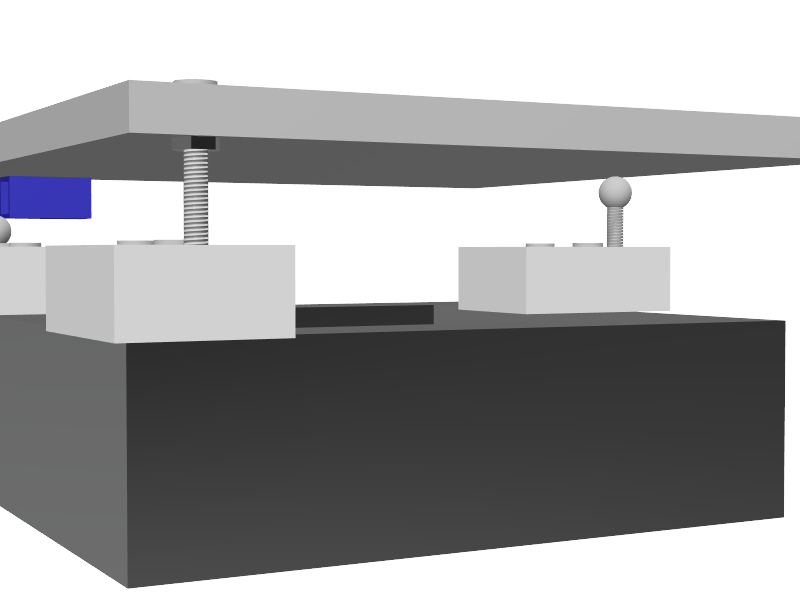
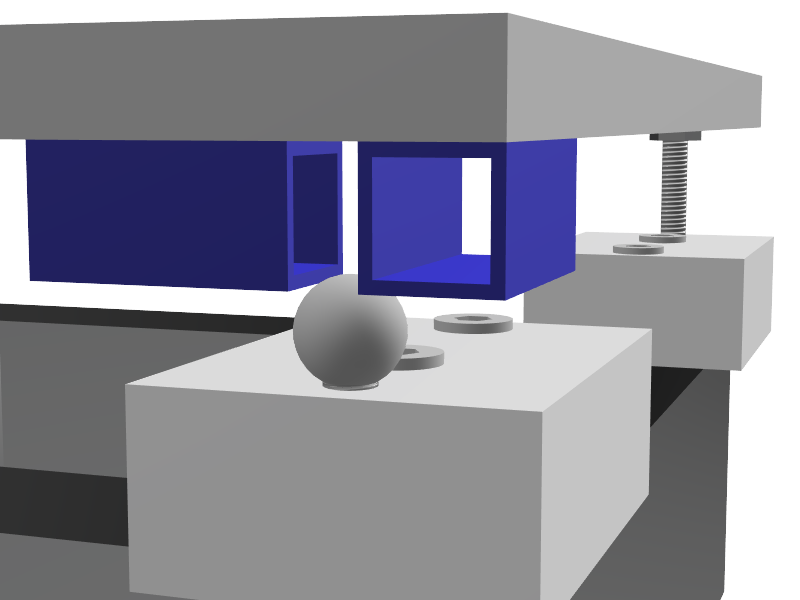
I want kinematic mount (like what @mrehorstdmd did on his printers), including PTFE blocks for thermal decoupling. However, I do not have access to a mill or basically any machine tools except a drill press. This made one of the three reference points (the one with the groove, only allowing lateral movement in one direction) a bit non-obvious.
One idea I came up with is using 10x10x1mm square tubing, as that's something I can easily buy locally. Those are shown in blue in the following images.


(Springs are still missing)After I finished that sketch, I realized that two M4 or M5 nuts (either hex or square), with a well-chosen distance between them, would probably serve the same purpose, but with less height being lost.
If someone has another idea, using easily availble standard parts, I'm all ears

-
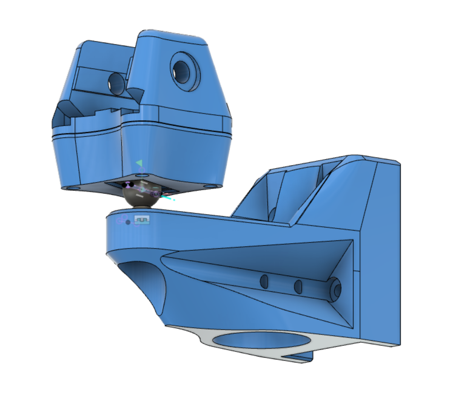
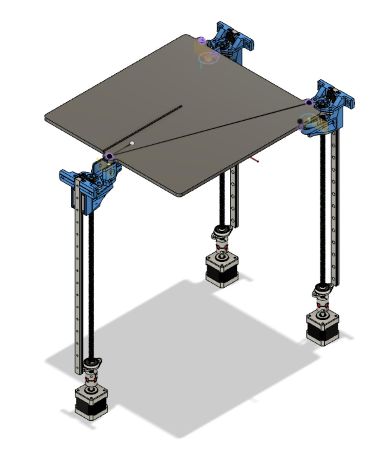
I'm currently working on a 3-lead kinematic Z axis for my CoreXY. I'm using short pieces of 2020 extrusion as thermal isolation between the bed (a repurposed Railcore 300ZL aluminum bed) and the printed mounts. Some blocks of drilled PTFE would work even better if there still ends up being too much conduction through the extrusion. I'm using neodymium magnets + magnetic ball joints for the 2, 1, and 0 linear dof mounts.


Still waiting for a few more parts to come in before I put it on the printer. By eliminating a rigid under-frame for the bed, I'm hoping I will be able to avoid some of the wear problems that can arise from having over-constrained Z rails, while retaining enough stability for reliable prints. In principle, it should also be possible to use the kinematic mount to help align the rails, by coating the magnets with some dry-erase marker, running the bed up and down, and seeing where the material rubs off. We'll see.

Happy to share design files if you're interested.
-
What you have designed, because its floating on 3 points (which is elegant), runs the risk of not running true to ANY of the linear constraints... you could end up with a bed that translates and rotates relative to all three axies as it moves in Z.
To prevent that, you would need to precisely align 3 rails on three separate planes, which themselves need to be precisely aligned to be at least parallel.
Possible, but a lot of work.
You also now have the issue of CPE in the screws compounding (only an issue if you buy cheap leadscrews though).The advantage of reducing the number of rails, is that you greatly reduce the challenge of aligning those rails relative to each other.
Lots of commercial printers use just 2 linear constraints and a single screw because of the need for a simple (hence cheap) assembly process. They then rely on the bed/frame stiffness to compensate for the cantilever.
The big advantage of rails on extrusions is that they can handle very high side-loads which means you can have just 2 rails and a large cantilever. Do that right and you only have to align 2 rails on the same piece of extrusion.
And given that good quality rails are expensive... fewer is generally better.All of which is probably academic, in an FDM printer, especially a home built one.
And for custom leadscrews. Misumi. Not cheap, but very high quality.
The number 1 issue I normally see is beds that are not tightly enough constrained in the x/y plane, so things move about and cause vertical ripples.
-
Thanks for the detailed comments! I’ll definitely report back with a full account when I get it together.
