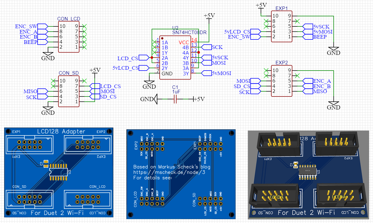
Logic Level shifter for 12864 display on Duet 2 Wifi
-
@oliof said in Logic Level shifter for 12864 display on Duet 2 Wifi:
3 weeks
ah, didn't realize you ordered them a that long ago, seemed like 3 days to me

(3 weeks is still quite good considering; I will likely need a break from banging my head against BLE 5 so can look over the 74hct08 layout one of these days np)

-
@oliof said in Logic Level shifter for 12864 display on Duet 2 Wifi:
I will be careful!
quick tip is to measure ground on the duet to ground on the lcd12864 before powering up, if continuity good ods, and grounds are usually easy to spot making it an quick and easy test for reversed wires.
-
@oliof said in Logic Level shifter for 12864 display on Duet 2 Wifi:
I may have left too little clearance for the headers.
option 2 is to cut off the 10 way IDC on the ribbon and replace with a 2x5 dupont style housing, or as I often end up, cutting down a 2x40 or laminating any combination of smaller housings (just make sure to align the release catch on the outside if you need to make alterations)
-
good tip on the dupont housing, as I have those in the house and my crimp success rate with duponts is above 80% (-:
-
@bearer enabling the LCD12864 feature for DuetNG in RepRapFirmware3 does not grow the size beyond rom, or at least I do not get an error message ... I still need to suss out the pin assignments though.
-
@oliof I thought it built ok the first time, but can't seem to reproduce the success.
feel free to try the changes I think I used..
index 11d2bdfc..1a8948c5 100644
--- a/src/DuetNG/Pins_DuetNG.h
+++ b/src/DuetNG/Pins_DuetNG.h
@@ -40,7 +40,7 @@ constexpr size_t NumFirmwareUpdateModules = 4;                // 3 modules, plus one for manua
 #define SUPPORT_IOBITS                 1                                       // set to support P parameter in G0/G1 commands
 #define SUPPORT_DHT_SENSOR             1                                       // set nonzero to support DHT temperature/humidity sensors
 #define SUPPORT_WORKPLACE_COORDINATES  1                       // set nonzero to support G10 L2 and G53..59
-#define SUPPORT_12864_LCD              0                                       // set nonzero to support 12864 LCD and rotary encoder
+#define SUPPORT_12864_LCD              1                                       // set nonzero to support 12864 LCD and rotary encoder
 #define SUPPORT_OBJECT_MODEL   1
 #define SUPPORT_FTP                            1
 #define SUPPORT_TELNET                 1
@@ -53,7 +53,7 @@ constexpr size_t NumFirmwareUpdateModules = 4;                // 3 modules, plus one for manua

 // The physical capabilities of the machine

-constexpr size_t NumDirectDrivers = 12;                                // The maximum number of drives supported directly by the electronics
+constexpr size_t NumDirectDrivers = 11;                                // The maximum number of drives supported directly by the electronics
 constexpr size_t MaxSmartDrivers = 10;                         // The maximum number of smart drivers

 constexpr size_t MaxSensors = 32;
@@ -112,18 +112,18 @@ constexpr Pin ENABLE_PINS[NumDirectDrivers] =
 {
        PortDPin(14), PortCPin(9), PortCPin(10), PortCPin(17), PortCPin(25),    // Duet
        PortDPin(23), PortDPin(24), PortDPin(25), PortDPin(26), PortBPin(14),   // DueX5
-       PortDPin(18), PortCPin(28)
                // CONN_LCD
+       PortDPin(18),
                // CONN_LCD  PortCPin(28)=EncoderPinB
 };
 constexpr Pin STEP_PINS[NumDirectDrivers] =
 {
        PortDPin(6), PortDPin(7), PortDPin(8), PortDPin(5), PortDPin(4),                // Duet
        PortDPin(2), PortDPin(1), PortDPin(0), PortDPin(3), PortDPin(27),               // DueX5
-       PortDPin(20), PortDPin(21)
                // CONN_LCD
+       PortDPin(20)
                        // CONN_LCD PortDPin(21)=LcdCSPin
 };
 constexpr Pin DIRECTION_PINS[NumDirectDrivers] =
 {      PortDPin(11), PortDPin(12), PortDPin(13), PortAPin(1), PortDPin(9),             // Duet
        PortDPin(28), PortDPin(22), PortDPin(16), PortDPin(17), PortCPin(0),    // DueX5
-       PortDPin(19), PortAPin(25)
                // CONN_LCD
+       PortDPin(19)
                        // CONN_LCD  PortAPin(25)=EncoderPinA
 };

 // Pin assignments etc. using USART1 in SPI mode
@@ -187,6 +187,25 @@ constexpr Pin SdWriteProtectPins[NumSdCards] = { NoPin, NoPin };
 constexpr Pin SdSpiCSPins[1] = { PortCPin(24) };
 constexpr uint32_t ExpectedSdCardSpeed = 20000000;

+// 12864 LCD
+// The ST7920 datasheet specifies minimum clock cycle time 400ns @ Vdd=4.5V, min. clock width 200ns high and 20ns low.
+// This assumes that the Vih specification is met, which is 0.7 * Vcc = 3.5V @ Vcc=5V
+// The Duet Maestro level shifts all 3 LCD signals to 5V, so we meet the Vih specification and can reliably run at 2MHz.
+// For other electronics, there are reports that operation with 3.3V LCD signals may work if you reduce the clock frequency.
+constexpr uint32_t LcdSpiClockFrequency = 2000000;             // 2.0MHz
+constexpr Pin LcdCSPin = PortDPin(21);      //connlcd.10 --> gate -> exp2.4
+constexpr Pin LcdBeepPin = PortAPin(8);     //connlcd.4           -> exp1.1
+constexpr Pin EncoderPinA = PortAPin(25);   //connlcd.8           -> exp2.5
+constexpr Pin EncoderPinB = PortCPin(28);   //connlcd.6           -> exp2.3
+constexpr Pin EncoderPinSw = PortAPin(7);   //connsd.7            -> exp1.2
+                                            //adittional spi wiring:
+                                            //connsd.6            <- exp2.1
+                                            //connsd.5   --> gate -> exp1.3
+                                            //            `->     -> exp2.6
+                                            //connsd.4   --> gate -> exp1.5
+                                            //            `->     -> exp2.2
+                                            //connsd.3            -> exp2.4
+
 // Enum to represent allowed types of pin access
 // We don't have a separate bit for servo, because Duet PWM-capable ports can be used for servos if they are on the Duet main board
 enum class PinCapability: uint8_t
@@ -291,8 +310,8 @@ constexpr PinEntry PinTable[] =
        { Z_PROBE_MOD_PIN, PinCapability::write, "zprobe.mod" },
        { ATX_POWER_PIN, PinCapability::write,  "pson" },
        { PortCPin(7),  PinCapability::rw,              "connlcd.encb,connlcd.3" },
-       { PortAPin(8),  PinCapability::rw,              "connlcd.enca,connlcd.4" },
-       { PortAPin(7),  PinCapability::rw,              "connsd.encsw,connsd.7" },
+       //{ PortAPin(8),        PinCapability::rw,              "connlcd.enca,connlcd.4" }, //LCD Beep
+       //{ PortAPin(7),        PinCapability::rw,              "connsd.encsw,connsd.7" }, //EncoderPinSw
        { PortBPin(6),  PinCapability::rw,              "exp.pb6,exp.29,duex.pb6" },
        { 211,                  PinCapability::rwpwm,   "duex.gp1" },
        { 210,                  PinCapability::rwpwm,   "duex.gp2" },
diff --git a/src/Version.h b/src/Version.h
index 54caf0df..cf783708 100644
--- a/src/Version.h
+++ b/src/Version.h
@@ -9,7 +9,7 @@
 #define SRC_VERSION_H_

 #ifndef VERSION
-# define MAIN_VERSION  "3.01-RC8"
+# define MAIN_VERSION  "3.01-RC8 LCD"
 # ifdef USE_CAN0
 #  define VERSION_SUFFIX       " (CAN0)"
 # else
@@ -19,7 +19,7 @@
 #endif

 #ifndef DATE
-# define DATE "2020-04-17b4"
+# define DATE "2020-04-20b1"
 #endif

 #define AUTHORS "reprappro, dc42, chrishamm, t3p3, dnewman, printm3d"
but it doesn't build at all unless the pins are defined?
-
@oliof said in Logic Level shifter for 12864 display on Duet 2 Wifi:
@bearer enabling the LCD12864 feature for DuetNG in RepRapFirmware3 does not grow the size beyond rom, or at least I do not get an error message ... I still need to suss out the pin assignments though.
The standard v3.01-dev branch build of Duet2CombinedFirmware has 19kB free. The 12864 code on the Duet Maestro build takes up 0x24E0 bytes of readonly data, 0x2840 bytes of code, 0x144 exception table and 0x130 exception index. Total 0x5F94, which is nearly 24K. So unless I have missed anything, it is too large by about 5Kb, which agrees with the message.
I've just managed to reduce the size of the standard 3.02 binary by 4.5kb, so now you are only about 0.5kb short. This will be in the next commit. You will need to update the CoreNG and freeRTOS projects as well as the RepRapFirmware project.
Possible ways to make it fit (EDITED):
- You could save 5kb space by removing the large font
- Compile the less critical parts of the firmware with option -Os instead of -O2
- Remove one of the less-used kinematics classes when 12864 support is enabled
- Remove the old 3/4/5-point bed compensation (I will probably do this myself soon anyway)
- Remove the support for async moves (see SUPPORT_ASYNC_MOVES) or IOBITS (SUPPORT_IOBITS) or scanner
- Separate the WiFi and Ethernet support into separate firmware binaries, as they were before I combined them.
-
Update: I just tried a build with the 12864 display enabled. It overflowed by 28 bytes! So it's close to fitting.
-
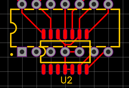
just occured to me, would adding both say DIP and SOIC footprint cause issues with signaling? if not, maybe it could lower the diy threshold a little, although SOIC shouldn't really be an issue for the beginner.

-
Funny story, the TXS0108 I ordered in DIP format came as SOIC on a PCB with pin headers ... same footprint, but kind of ironic.
-
@dc42 I was considering removing kinematics I don't need for the machine I want to run this on because it will likely be the easiest self-contained change for someone not super acquainted with the firmware. But finding another 28 bytes to drop seems a worthy cause (-:
-
eBay is like a box of chocolates?
btw, compiling without, say hangprinter , results in a binary after dc42's other improvements. seemed the path of least resistance.
diff --git a/src/Movement/Kinematics/Kinematics.cpp b/src/Movement/Kinematics/Kinematics.cpp index 782bd43f..d48ef90f 100644 --- a/src/Movement/Kinematics/Kinematics.cpp +++ b/src/Movement/Kinematics/Kinematics.cpp @@ -11,7 +11,9 @@ #include "LinearDeltaKinematics.h" #include "RotaryDeltaKinematics.h" #include "ScaraKinematics.h" +#ifndef SUPPORT_12864_LCD #include "HangprinterKinematics.h" +#endif #include "PolarKinematics.h" #include "FiveBarScaraKinematics.h" @@ -161,8 +163,10 @@ AxesBitmap Kinematics::GetConnectedAxes(size_t axis) const noexcept return new LinearDeltaKinematics(); case KinematicsType::scara: return new ScaraKinematics(); +#ifndef SUPPORT_12864_LCD case KinematicsType::hangprinter: return new HangprinterKinematics(); +#endif case KinematicsType::polar: return new PolarKinematics(); case KinematicsType::rotaryDelta: diff --git a/src/Movement/Kinematics/Kinematics.h b/src/Movement/Kinematics/Kinematics.h index e2cf603f..6852214e 100644 --- a/src/Movement/Kinematics/Kinematics.h +++ b/src/Movement/Kinematics/Kinematics.h @@ -27,7 +27,9 @@ enum class KinematicsType : uint8_t linearDelta, scara, coreXYU, +#ifndef SUPPORT_12864_LCD hangprinter, +#endif polar, coreXYUV, fiveBarScara, // was previously reserved for @sga, see https://forum.duet3d.com/topic/5775/aditional-carterian-z-axis-on-delta-printer -
@bearer said in Logic Level shifter for 12864 display on Duet 2 Wifi:
but it doesn't build at all unless the pins are defined?
I defined the freed pins from the stepper, so they weren't undefined. I just didn't sort them out. I'll give your patch a go and see whether I can get the 28 byte overflow.
-
After some more fighting with Eclipse, I seem to have a finished build from RepRapFirmware v3.01-dev branch with LCD support and no hangprinter ... will try to see whether my Duet2 board boots, and then carefully start a test setup ...
-
Took a while before I realized I had to go via 3.0 release to get the iap file to support the 3.x binaries; and then make the swap of the two pins I did on mine - but seems to work with RRF3 as well after Davids efforts.
The dedication on that man ... can we (temporarily!) put him to work on a covid-19 vaccine?
-
I am currently trying to understand your tsx cabling -- my 74hct08 started smelling funny after a minute when I tried to figure out what to connect where so I don't trust it a lot. Of course I am complicating things by using an 12864 minipanel which might not even work fine (but in testing lit up fine on 3.3V -- that may be just the leds though).
-
Also, some confusion: In your photo you are connecting to the CONN_SD port, not to the CONN_LCD one. Or am I looking at things wrong?
-
@oliof said in Logic Level shifter for 12864 display on Duet 2 Wifi:
Also, some confusion: In your photo you are connecting to the CONN_SD port, not to the CONN_LCD one. Or am I looking at things wrong?
@bearer said in Logic Level shifter for 12864 display on Duet 2 Wifi:
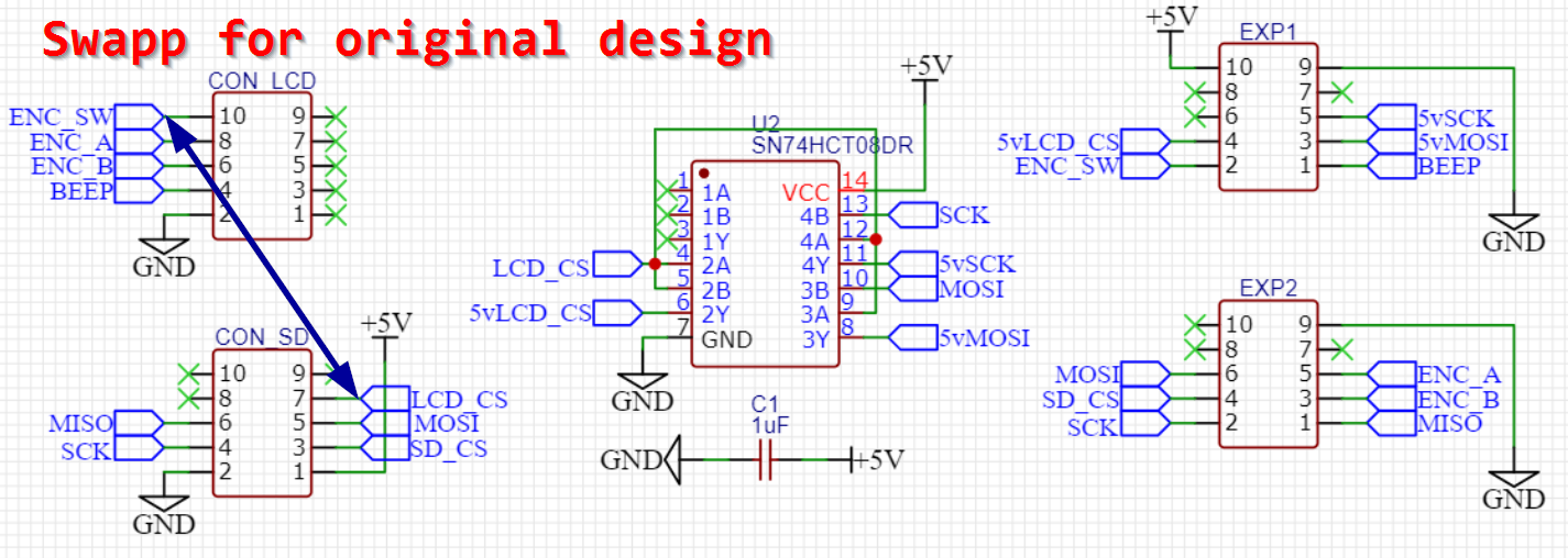
edit: i would propose swapping lcd_cs to from PortDPin(21) / lcdconn.10 to PortAPin(7) / sdconn.7 as it would enable a single 10 way ribbon cable to function as just a display + sd reader (but no buttons/beep). Or maybe utxd0, urxd0 and spi0_cs could be used if the reader isn't present or needed.
true story. the SPI bus is on CONN_SD

-
@oliof said in Logic Level shifter for 12864 display on Duet 2 Wifi:
I am currently trying to understand your tsx cabling -- my 74hct08 started smelling funny
the only difference is the swapping of the LCD_CS pin as it allowed me to use just the one port and also cleaned up the board layout a little. i could probably get below 3 vias if I really put some more effort into it, but with the prices jlcpcb have these days meh.
funny smelling wouldn't be caused by swapping the signal pins they don't have the oompfh to do so. i'd check the 5v and gnd connections.
-
It might be a mistake on my board. My guess is I can try to get it to work like your setup, and then move to my board or the updated design later.
I think the distribution of pins to headers is just what a standard 12864 display has, and not dc42's design. I'd suggest sticking with the standard setup.
Don't you need both headers still if you also want to use the encoder wheel? I'd question the utility of the 12864 display without one ... but I might be completely wrong. Speaking of the encoder, do I interpret your color scheme correctly that ENC_A, ENC_B, ENC_SW do not go through the level shifter but connect directly?