BLTouch V3.0 Information, Setup, and O'Scope Pictures
-
@zapta said in BLTouch V3.0 Information, Setup, and O'Scope Pictures:
The first waveform seems to have ac coupling. I presume that the oscilloscope was set to DC coupling.
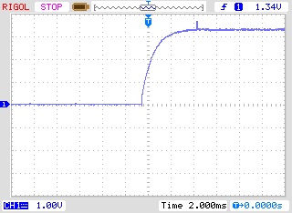
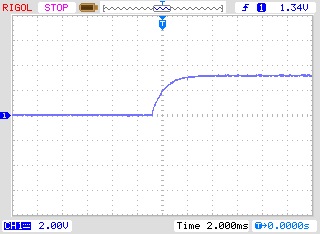
All the measurements were done with DC coupling. I'm thinking the weird waveform might be the result of no pull-up resistor, as referred to by @pipersw.
I've done some more measurements, this time with the BLTouch's output connected to the board and o'scope. Before I had it connected to the o'scope alone. This yielded much different results. Does the Duet Maestro have a built-in pull-up resistor?

Above is with the output connected to the board in "Logic Free" mode. This waveform looks much more sensible and is at around 3V, not the previous 1V when it was unconnected.
This is with the BLTouch in the 5V Logic Mode, but to my suprise, it seems to only show about 3V. Is that because of the clamping diodes, @pipersw? -
@jadonm said in BLTouch V3.0 Information, Setup, and O'Scope Pictures:
Does the Duet Maestro have a built-in pull-up resistor?
Not an expert, but it may be this: https://i.imgur.com/jPdCPKm.png
From second page of this PDF https://github.com/T3P3/Duet/blob/master/Duet2/Duet2Maestro_v1.0/Duet2Maestro_Schematic_v1.0.pdf
-
The Z probe input of the Maestro has an internal pull up resistor inside the microcontroller, value about 100K. I am fairly sure that it is enabled when you select BLTouch probe mode, but I will check.
-
@jadonm Yes, it's the clamping diode whose stuck at 3.3V.
-
@dc42 said in BLTouch V3.0 Information, Setup, and O'Scope Pictures:
The Z probe input of the Maestro has an internal pull up resistor inside the microcontroller, value about 100K. I am fairly sure that it is enabled when you select BLTouch probe mode, but I will check.
On schematic of Maestro, there is a external 10k pull-up, so the internal pull-up of the processor is don't care if enabled or not, because it's around 10k in all case.
-
@pipersw said in BLTouch V3.0 Information, Setup, and O'Scope Pictures:
On schematic of Maestro, there is a external 10k pull-up, so the internal pull-up of the processor is don't care if enabled or not, because it's around 10k in all case.
If you mean R62, that's a 10K series resistor, not a pullup resistor.
I have confirmed that the internal pullup resistor is enabled when BLTouch mode is selected.
-
@dc42 No, if I take the picture
 , I mean R70.
 -
That's the Z endstop connector, not the Z probe connector.
-
you are right !
-
I have a V3 bltouch installed as per setup guide for the Maestro. When I turn on the board to BL blinks with an error, I have to turn the board off and on several times before it will do a self test. No resistor is used.
-
@cabal2000, was the bed too close to the nozzle when you turn it on? If the BLT doesn't have sufficient mechanical clearance on power up, it enters an error state and blinks. I added to my homeall script a BLT error reset command I found in one of the threads here.
M280 P3 S160 I1 -
@cabal2000 My newest BLTouch does the same thing for me but it will work after turning the printer off and back on once.
-
@zapta Nozzle is no where close to the bed, pin is free. But I will be adding the reset command. Thanks man
-
@JadonM Would you be able to share which pins you are using for your setup? I am having some odd issues and want to try to emulate your setup.
-
@jaurand said in BLTouch V3.0 Information, Setup, and O'Scope Pictures:
@JadonM Would you be able to share which pins you are using for your setup? I am having some odd issues and want to try to emulate your setup.
Absolutely! I would love to have some novel wiring scheme that would solve all your problems, but unfortunately, I've just followed the wiki!
 I have the Maestro, which takes different wiring than the Wifi, Ethernet, or Duet3.
My wiring is all on the Z-probe connector and consists of:
BLTouch Out - Maestro In
GND - GND
Control - MOD
5V - 5VHopefully that is a help to you, and feel free to ask me any other questions you have!
-
@JadonM Thank you for the o'scope images
I followed this setup https://betrue3d.dk/bltouch-on-duet-wifi-configuratio-and-usage/ for duet wifi and am unsure about the pins to use for bltouch error reset and 5V logic mode for the duet wifi
I keep getting a flashing red duty cycle and when i run mesh bed it runs for a bit then the probe stays in the up position.
-
@jaurand said in BLTouch V3.0 Information, Setup, and O'Scope Pictures:
@JadonM Thank you for the o'scope images
I followed this setup https://betrue3d.dk/bltouch-on-duet-wifi-configuratio-and-usage/ for duet wifi and am unsure about the pins to use for bltouch error reset and 5V logic mode for the duet wifi
I keep getting a flashing red duty cycle and when i run mesh bed it runs for a bit then the probe stays in the up position.
I'm sorry, but I don't think I know enough about the Duet and BLTouch to answer your question. I would recommend making a new thread with all the details and one of the much more knowledgeable regulars can help you.
Sorry that I can't help you!
-
@JadonM that is plenty of help enough! Thank you!