@chrishamm Ok i figured out the problem. When i have the folder with all the required files in it, like dsf, sd and plugin.json for example, I need to compress the files inside the folder directly and not the folder itself. Don't know, it looks the same when you decompress it and everything but i guess there's a difference. Hope that makes sense. Anyway, thanks for your help. You can close this topic now.
Posts made by Sevimuelli
-
RE: External plugin not uploading after compressing myselfposted in Duet Web Control
-
External plugin not uploading after compressing myselfposted in Duet Web Control
Hi
I wanted to change some settings on a plugin before uploading. But I noticed that when I compress the plugin myself, it won't upload. For testing, I tried the Endstop plugin. I decompressed it and compressed it again without changing anything. I think it uploads it but the window for the plugin installation doesn't show up. I'm using a Mac and thought maybe there is a problem with that and tried it with Linux as well but no success.
I am sure it is just a stupid mistake from my side but I can't figure it out. It's like it can't find the plugin.json file i guess. Do I need some special argument when compressing the folder? In the documentation it only says compressing, nothing special about it.
Any help is appreciated.
Many thanks,
Sevi -
RE: Additional axis not homing after print finishedposted in General Discussion
@gloomyandy Considering the relative mode, in the homedelta.g file, the mode is set to relative mode anyway, so it shouldn't make a difference. But I have to do some more testing on this. I'm actually not home now but will be back next week. I will write my findings here.
I don't think hiding the axis is a solution as this axis are always physically connected to each other and under normal conditions it works fine.
And no, the endstop can not be the problem. The endstop is on the top and the U axis is far down so it is not possible.
Anyway, I appreciate your help very much. Thank you. Hope I can figure this one out somehow.
-
RE: Additional axis not homing after print finishedposted in General Discussion
@gloomyandy Yes, it it linked.
First, you define the drive for the new axis like any other:
; Drives
M569 P0.2 S1                                          ; physical drive 0.2 goes forwards
M569 P0.3 S1                                          ; physical drive 0.3 goes forwards
M569 P0.4 S1                                          ; physical drive 0.4 goes forwards
M569 P0.0 S0                                          ; physical drive 0.0 goes forwards
M569 P0.1 S1                                          ; physical drive 0.1 goes forwards
M584 X0.2 Y0.3 Z0.4 E0.1 U0.0                         ; set drive mapping
M350 X16 Y16 Z16 E16 U16 I1                           ; configure microstepping with interpolation
M92 X160.00 Y160.00 Z160.00 E391.388 U250.0           ; set steps per mm
M566 X500.00 Y500.00 Z500.00 E600.00 U500             ; set maximum instantaneous speed changes (mm/min)
M203 X18500.00 Y18500.00 Z18500.00 E10000 U6000       ; set maximum speeds (mm/min)
M201 X5000.00 Y5000.00 Z5000.00 E5000.00 U2000        ; set accelerations (mm/s^2)
M906 X1800 Y1800 Z1800 E1300 U1900 I30                ; set motor currents (mA) and motor idle factor in per cent
M84 S30                                               ; Set idle timeout
Then, you have the delta configuration, but instead of only setting the three rod lengths for delta, you also set a fourth value in the "L" parameter, the distance between the extruder output and the filament entry point on the hot end. So roughly the distance between the center of the head and the extruder.
Then you set the X and Y offset of the extruder to the hotend. There isn't a correct value for this but rather a try and error between distance, offset, and homing height of the additional axis, until you found a satisfying solution. Then, the firmware will always keep the distance specified when moving around, all based on the head, No matter how you move the head around, manual, in print, the additional axis will always follow.; Delta config M665 R243.301 L440.45:440.45:440.45:400 B145 H405 ; Set delta radius, diagonal rod length, printable radius and homed height M666 X0 Y0 Z0 U0 ; Put your endstop adjustments here, or let auto calibration find them ;M669 K3 X0 Y-150 ;M669 X0 Y-150 ; Addidtional axis offset M669 X0 Y-50 ; Additional axis offsetSmall side question, in the Gcode M669, there are two parameters:
Snnn Segments per second (RRF 3.3 and later)
Tnnn Minimum segment length (mm) (RRF 3.3 and later)
I'm not really sure how they work. I know that normally you don't need to use this. As far as I understand, they specify how fast and accurate the new axis follows, but I haven't found any explanation really. Do you happen to know what they are exactly? -
RE: Additional axis not homing after print finishedposted in General Discussion
@gloomyandy Thank you for your response. I only press the "Home all" button in the Dashboard, as i always do when homing. No automatic homing or anything for now. This always works except after the print is finished. I also think it happens if i cancel the print in between and want to home the printer. I use Simplify3D for slicing if that makes a difference.
My homedelta.g file:
; homedelta.g
; called to home all towers on a delta printer
;
; generated by RepRapFirmware Configuration Tool v3.3.13 on Fri Sep 16 2022 22:17:44 GMT+0200 (Central European Summer Time)
G91                        ; relative positioning
G1 H1 X685 Y685 Z685 U630 F2000 ; move all towers to the high end stopping at the endstops (first pass)
G1 H2 X-5 Y-5 Z-5 U-5 F400    ; go down a few mm
G1 H1 X10 Y10 Z10 U10 F100     ; move all towers up once more (second pass)
G1 Z-5 U-5 F300               ; move down a few mm so that the nozzle can be centred
;
;G1 H1 U500 F200 		       ;  move to the high end stopping at the endstops (first pass)
;G1 H2 U-5 F300 			       ; go down a few mm
;G1 H1 U10 F100      	     ; move up once more (second pass)
;G1 H2 U-5 F300 			       ; move down a few mm
;
G90                        ; absolute positioning
G1 X0 Y0 F2000             ; move X+Y to the centre
Begin of gcode file:
G90           ; Set to absolute positioning
M83          ; Set extruder to relative mode
M106 S0 P0    ; Turn of fan
M140 S50       ; Set bed temperature
M190 S50       ; Wait for bed temperature
M104 S210 T0   ; Set extruder temp
M109 S210 T0   ; Wait for extruder temp
;G28 ; home all axes
; process Process 1
; layer 1, Z = 0.1600
T0
G1 E-2.0000 F3000
; feature skirt
; tool H0.1600 W0.504
G1 Z0.5000 F1200
G1 X90.031 Y61.756 F6000
G1 Z0.1600 F1200
G1 E2.0000 F3000
G1 X-90.031 Y61.756 E5.9160 F1200
G1 X-90.741 Y61.716 E0.0234
End of a gcode file:
G1 X94.734 Y55.497 E0.0197
G1 X94.703 Y55.692 E0.0077
G1 X94.703 Y-55.492 E4.3488
G1 X94.703 Y-55.692 F1782
G1 E-2.0000 F3000
; layer end
M104 S0 ; turn off extruder
M140 S0 ; turn off bed
;M84 ; disable motors
G91;   Set to Relative Positioning
G1 Z20; Move Head 20mm up
; Build Summary
;   Build Time: 6 hours 48 minutes
;   Material Length: 39990.7 mm (39.99 m)
;   Material Volume: 96189.0 mm^3 (96.19 cc)
;   Material Weight: 120.24 g (0.27 lb)
;   Material Cost: 5.53
I don't think i have anything else special about homing in my printer. When this error occurs, I push the emergency stop, which powers off the 24V part and also resets the board via a trigger configured as emergency stop. After that everything works again.
-
Additional axis not homing after print finishedposted in General Discussion
Hi
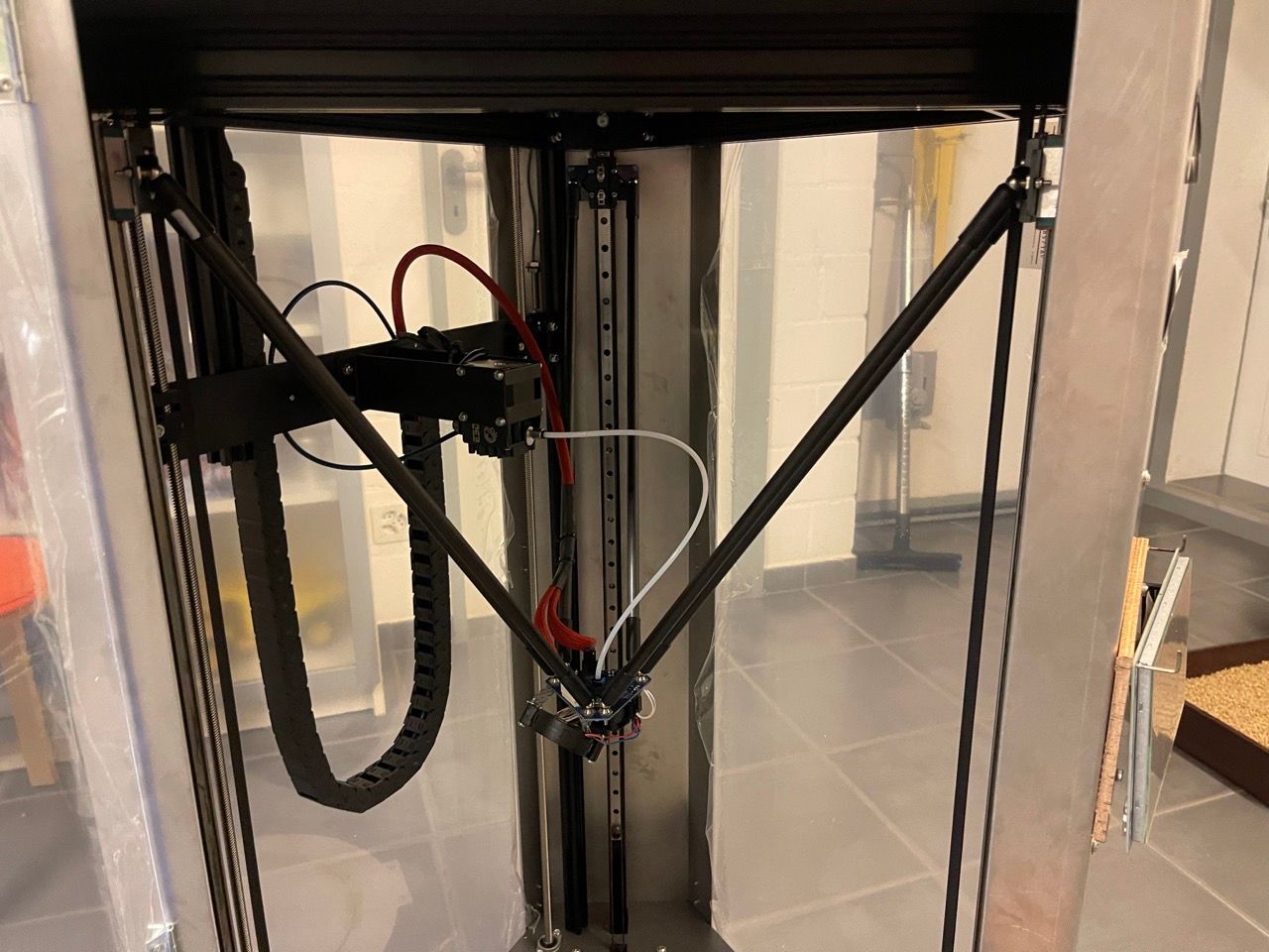
I have a delta printer with a Duet 3 Mini in a SBC setup together with a Raspberry Pi. There I have an additional axis for the extruder. Everything is configured correctly and moves as expected, for homing, printing and when moving manually. But when the print job is finished and I want to home the printer again, to bring the head out of the way, the additional axis doesn't move. The three main axis X, Y, Z home all as expected but the additional axis stays still, which is off course problematic as it will just rip off the cables and tubes. Good thing I added an emergency stop
When i started testing this new setup, I was running Firmware 3.4.4, upgraded later to 3.4.5 and am currently running 3.5.0-beta.3. Same versions for Duet Web Control and DSF. The issue existed from the beginning and nothing changed with any version. I also don't get any error messages or anything. The motor is not hot and moves normally without any issue. And it's not a thing that happens from time to time but every time and only after a job is finished and I want to home the printer.
Here my config:
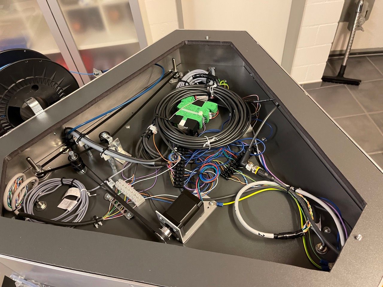
config.gHere are some pictures of my setup, not the most recent ones but the basic principle is the same:


Any ideas on why this is happening? Does anybody else experience this issue?
Many thanks,
Sevi -
RE: Disable Bed Compensation (M561) disabled / greyed outposted in Duet Web Control
@droftarts Thanks for the explanation! Ok now it makes sense because I am running DWC 3.4.5 and it never worked.
I have to agree with @jay_s_uk that it's a bit pointless if both do the "same" thing. Looking at the dev-version, both buttons are now active only when the mesh compensation is active. And yes you can disable the bed calibration as it just resets the bed probing as described in the G Code reference but for this to be useful it needs to be active as soon as a calibration is active. But then again you can just home the printer and it has the same effect. Don't get me wrong but I feel like now it's more confusing than helpful. But that's not my place to decide.Sevi
-
RE: Disable Bed Compensation (M561) disabled / greyed outposted in Duet Web Control
@droftarts @jay_s_uk Thanks for the replies. Yes I understand how it should work and what's the difference between calibration and compensation. The issue here is that this button can never be enabled because it is only enabled if the object property "move.compensation.type" is set to "Point". That's how they have done it in DuetWebControl:
<v-list-item :disabled="!move.compensation.type || move.compensation.type.indexOf('Point') === -1" @click="sendCode('M561')">
    <v-icon class="mr-1">mdi-border-none</v-icon> {{ $t('panel.movement.disableBedCompensation') }}
</v-list-item>
But if you check the source code of reprapfirmware, the type will only ever be set to either "none" if no mesh bed compensation ( no matter what about the calibration) or to "mesh" if a mesh bed compensation is active. There is no option for "Point".
So the main issue is that right now you have a button which never can be active. It is not possible. Yeah sure one option is to just remove this button, but in my opinion, it would be really helpful to have some sort of indication if a calibration is active or not. Use this button for what is originally was intended for.
I would make a new issue on GitHub, but I'd like to know what it's actually about this button. I could even make a pull request for DuetWebControl, it's an easy fix. But for this to work one needs a corresponding property in the object model and to be honest, I feel less comfortable changing something in the reprap firmware.
Sevi
-
Disable Bed Compensation (M561) disabled / greyed outposted in Duet Web Control
Hi
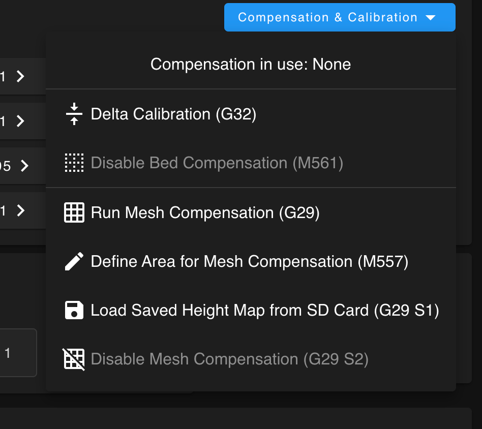
On the Dashboard under Compensation & Calibration, the field "Disable Bed Compensation (M561)" is constantly disabled. As far as I understand, ones one does a calibration with G32 ( not a Mesh Compensation), this field should be active and one should be able to deactivate the previous calibration.
 Screenshot 2023-04-04 at 13.34.55.png
Looking into the source code, under MovementPanel.vue, this field is disabled if: "!move.compensation.type || move.compensation.type.indexOf('Point') === -1". So if the mesh grid compensation is active, this field should be available. But even then, the field is disabled because ".indexOf('Point')" always returns -1, because type can only be "none" or "mesh". This behaviour is probably wrong anyway, because this button corresponds to the G32 calibration and not to the mesh compensation. Or am I not seeing something here? So if after calibration the type would be set to "Point", it would work but then again as far as I understand, this would be in the wrong category. So one needs a property "Type" under move.calibration, not move.compensation, as this are two different categories, right? And to be completely correct, shouldn't it say something like "Disable Bed Calibration" to differentiate between this and mesh compensation?
So with the proper values in the object model, this will be an easy fix. But as long as they are not available, one can't do anything about it.
I have updated the system today and run Duet Web Control 3.4.5. I use Duet3D with a Delta 3D printer.
Thanks very much in advance

-
RE: Duet3 Monitor PWM fan operation?posted in General Discussion
@dc42 Hi, I am working on a similar issue. I have a chamber heater with a 4-wire fan. I have one temp sensor in the chamber for regulating heating and one temp sensor on the heater itself, which shuts down the heater if it exceeds 100 Degrees. I also have a thermal fuse on the heater just in case. So its already pretty safe. I would like to monitor the fan and if it stops working or goes below a certain threshold, I get a fan failure and with that a heater failure. Thus the 4-wire fan. I think this would really help safety. Is there any possibility to do so?
If not, I imagine this would be a nice addition.