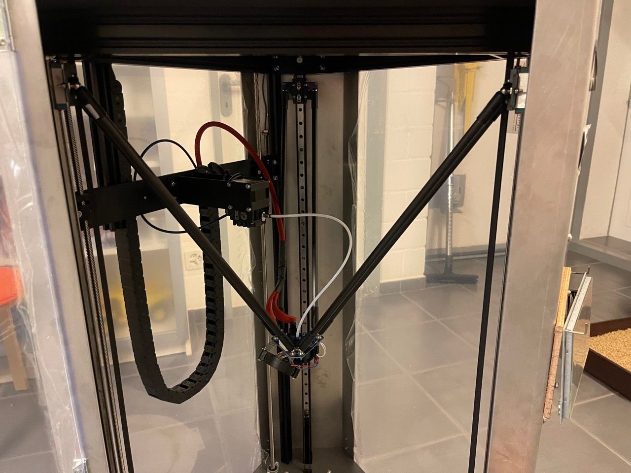
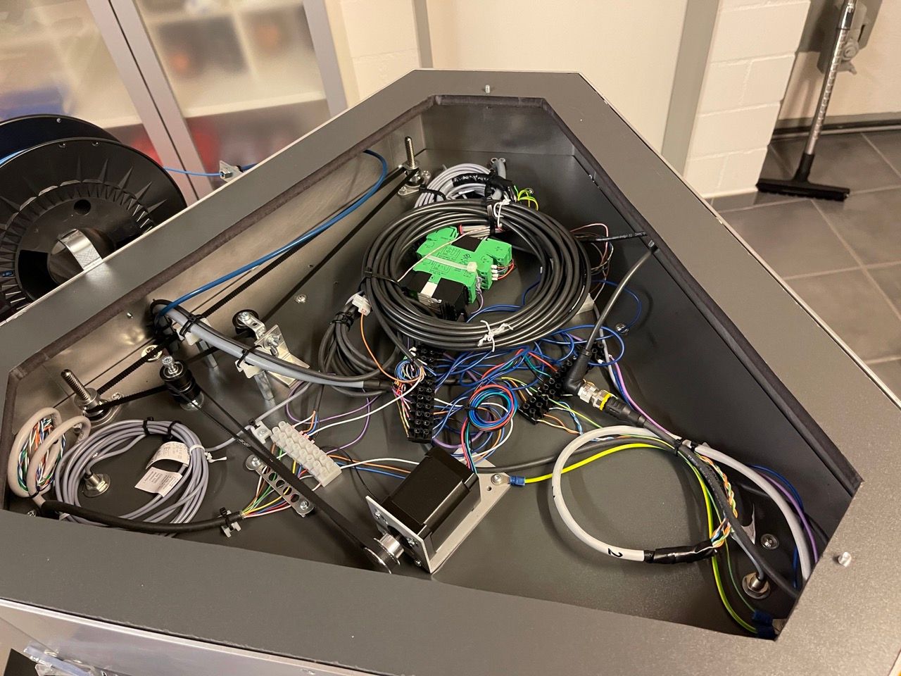
@gloomyandy Yes, it it linked.
First, you define the drive for the new axis like any other:
; Drives
M569 P0.2 S1                                          ; physical drive 0.2 goes forwards
M569 P0.3 S1                                          ; physical drive 0.3 goes forwards
M569 P0.4 S1                                          ; physical drive 0.4 goes forwards
M569 P0.0 S0                                          ; physical drive 0.0 goes forwards
M569 P0.1 S1                                          ; physical drive 0.1 goes forwards
M584 X0.2 Y0.3 Z0.4 E0.1 U0.0                         ; set drive mapping
M350 X16 Y16 Z16 E16 U16 I1                           ; configure microstepping with interpolation
M92 X160.00 Y160.00 Z160.00 E391.388 U250.0           ; set steps per mm
M566 X500.00 Y500.00 Z500.00 E600.00 U500             ; set maximum instantaneous speed changes (mm/min)
M203 X18500.00 Y18500.00 Z18500.00 E10000 U6000       ; set maximum speeds (mm/min)
M201 X5000.00 Y5000.00 Z5000.00 E5000.00 U2000        ; set accelerations (mm/s^2)
M906 X1800 Y1800 Z1800 E1300 U1900 I30                ; set motor currents (mA) and motor idle factor in per cent
M84 S30                                               ; Set idle timeout
Then, you have the delta configuration, but instead of only setting the three rod lengths for delta, you also set a fourth value in the "L" parameter, the distance between the extruder output and the filament entry point on the hot end. So roughly the distance between the center of the head and the extruder.
Then you set the X and Y offset of the extruder to the hotend. There isn't a correct value for this but rather a try and error between distance, offset, and homing height of the additional axis, until you found a satisfying solution. Then, the firmware will always keep the distance specified when moving around, all based on the head, No matter how you move the head around, manual, in print, the additional axis will always follow.
; Delta config
M665 R243.301 L440.45:440.45:440.45:400 B145 H405     ; Set delta radius, diagonal rod length, printable radius and homed height
M666 X0 Y0 Z0 U0                                      ; Put your endstop adjustments here, or let auto calibration find them
;M669 K3 X0 Y-150
;M669 X0 Y-150                                         ; Addidtional axis offset
M669 X0 Y-50                                         ; Additional axis offset
Small side question, in the Gcode M669, there are two parameters:
Snnn Segments per second (RRF 3.3 and later)
Tnnn Minimum segment length (mm) (RRF 3.3 and later)
I'm not really sure how they work. I know that normally you don't need to use this. As far as I understand, they specify how fast and accurate the new axis follows, but I haven't found any explanation really. Do you happen to know what they are exactly?


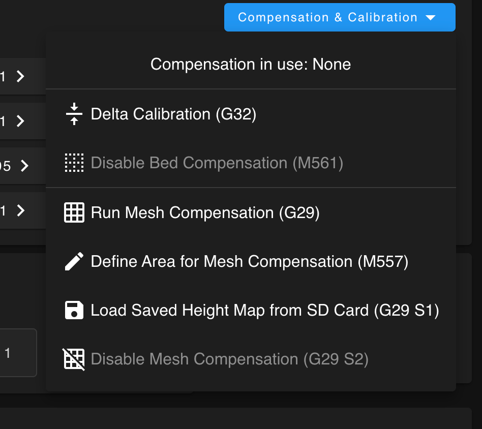
 Screenshot 2023-04-04 at 13.34.55.png