I changed it to M308 S2 P"e1temp" Y"thermistor" A"Heat Sink" and it works now. Wonder why E3D calls it a PT1000?
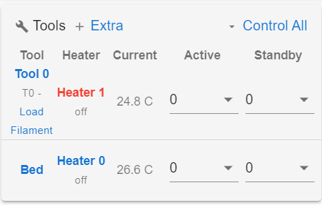
Is there a way to get it to show up with Tool 0 and Bed so I do not need to push the "Extra" button to see the temp?
I changed it to M308 S2 P"e1temp" Y"thermistor" A"Heat Sink" and it works now. Wonder why E3D calls it a PT1000?
Is there a way to get it to show up with Tool 0 and Bed so I do not need to push the "Extra" button to see the temp?

I checked the resistance and it is 95K at room temperature. It is plugged into the connector next to the heater block.
I add the line below but it looks like it is reading 2000C. How do I fix this?
M308 S2 P"e1temp" Y"pt1000" A"Heat Sink"
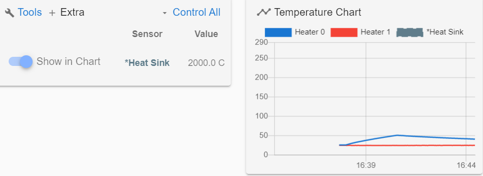
I am making an Extruder and want to use a PT1000 to measure heat creep in the heat sink with different fans/heat sink designs. IF I connect the PT1000 to E1 on the Duet board how do I change the config file so I can see all three temperatures, bed, extruder and heat sink?
Broad is a Duet 2 WIFI running 3.0 firmware.
From current config file:
; Heaters
M308 S0 P"bedtemp" Y"thermistor" T100000 B4725 C7.06e-8 ; configure sensor 0 as thermistor on pin bedtemp
M950 H0 C"bedheat" T0 ; create bed heater output on bedheat and map it to sensor 0
M143 H0 S130 ; set temperature limit for heater 0 to 130C
M307 H0 B0 S1.00 ; disable bang-bang mode for the bed heater and set PWM limit
M140 H0 ; map heated bed to heater 0
M308 S1 P"e0temp" Y"thermistor" T100000 B4725 C7.06e-8 ; configure sensor 1 as thermistor on pin e0temp
M950 H1 C"e0heat" T1 ; create nozzle heater output on e0heat and map it to sensor 1
M143 H1 S275 ; set temperature limit for heater 1 to 275C
M307 H1 B0 S1.00 ; disable bang-bang mode for heater and set PWM limit
Ok that makes sense. I was wondering why this was in the spread sheet and now I know.
Thanks
I been playing with M592 and did not get what I was expecting but think it should work. I will test print tomorrow and let you know if it helps.
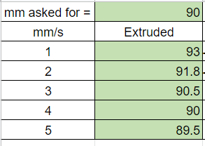
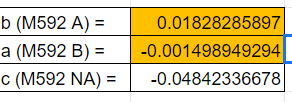
I made the program below to move XY and E and measured how much filament is pulled. I ran it without M592 to get the numbers for the spread sheet. I have used the spread sheet found in other threads and came up with M592 A.018 B-.0015. My printer is a ANET A8. I left the default steps/mm at E100 for the tests and turned presaure advance off.
PROGRAM:
M104 S240 ; set temperature
M98 P"homeall.g"
G1 Z25.0 F1500 ;Move the platform down 25mm
G1 X10 Y10 F1500
M204 S760 ;Acceleration
M572 D0 S0.0 ;Preasure Advance
M592 D0 A.0183 B-.0015
M109 S240 ; set temperature and wait for it to be reached
G21 ; set units to millimeters
G90 ; use absolute coordinates
M82 ; use absolute distances for extrusion
G92 E0
;1mm/s=60MM/MIN
;2mm/s=120MM/MIN
;3mm/s=180MM/MIN
;4mm/s=240MM/MIN
;5mm/s=300MM/MIN
G1 X110 Y110 E90 F300
M104 S0 ;extruder heater off
M98 P"homex.g"
M84 ;steppers off
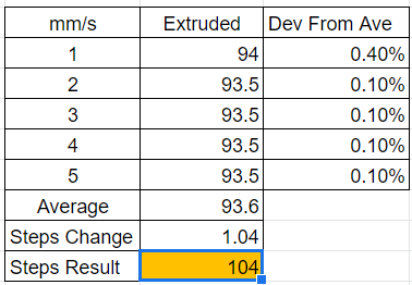
With M592 D0 A.0183 B-.0015 I get the following:
1mm/s = 94mm pulled
2mm/s = 93.5mm pulled
3mm/s =93.5mm pulled
4mm/s =93.5mm pulled
5mm/s =93.5mm pulled
I expected M592 to get all feed rates closer to 90mm pulled. Any ideas why it did not do what I expected? I know I can change the steps per mm for E. Couldn't a formula be such that A and B would put the calibration to 90mm?
@Phaedrux said in How to Set Z home:
Can you post your homing files? Maybe your full config.g too.
Do you mean that the nozzle is pushing into the bed surface? How are you measuring -0.3?
When you trigger the endstop the position is set to either the minima or maxima from M208. So triggering the zmin endstop should set the position to -0.3 as you have that as your minima. Unless it's being reset with an G92 Z after hitting the endstop.
The G92 Z0 was resetting it in the homeall.g and homez.g files. I commented out ;G92 Zxxx and now when it is on the Z end stop it shows what is in M208 below Thanks!
M208 X-33 Y-10 Z-0.3 S1
Not sure why G92 Z-.03 did not work. I use G92 on mills at work sounds like it should do the same thing on the printer.
G92 "Change Work Coordinate System"
G92 X0 Y0 Z=VTOFH[VTLCN]+12.7
This would set where the spindle is now to X0 Y0 and Z would be the current tool in the spindles length+12.7
I am using a switch to home XYZ. When I home Z the nozzle is about .3mm below the bed. I have been trying figure out how to set it so it knows this. When I home XY the web interface shows X-33 Y-10 but Z still shows Z0.0.
; Axis Limits
M208 X-33 Y-10 Z-0.3 S1 ; set axis minima
M208 X220 Y220 Z240 S0 ; set axis maxima
I also tried editing the homeZ.g and the homeall.g
G92 Z0.3 ; set Z position to axis minimum (you may want to adjust this)
What am I doing Wrong?
Thanks
How do I setup Cura to post the Fan on after the first layer? Cura is putting in M107 and M106 S255
I have the Duet2 Ethernet setup on my printer. I an now working on the start and end code to put in Cura. I am running the newest firmware 3.0. I have the Extruder fan plugged into FAN0 and part fan in FAN1.
The Extruder fan will turn on and off when the hot end reaches the set temp. I usually do not want the part fan to turn on until the first layer is finished. I know I could set T to a large number at the start but how do I get this setup so Cura will turn it on after the first layer?
; Fans
M950 F0 C"fan0" Q500 ; create fan 0 on pin fan0 and set its frequency
M106 P0 S0 H T60 ; set fan 0 value. Thermostatic control is turned on
M950 F1 C"fan1" Q500 ; create fan 1 on pin fan1 and set its frequency
M106 P1 S1 H1 T60 ; set fan 1 value. Thermostatic control is turned on
@Phaedrux said in Duet 2 Ethernet Setup Warning.:
Is your Z connected correctly? The X and Y homing files probably have a Z move to lift the head out of the way for travel. If the Z axis isn't connected correctly you could get those warnings.
You were right Z moves up and then back down when X and Y are home individually. The warning does not happen now Thanks!
@dc42 said in Duet 2 Ethernet Setup Warning.:
@Keith53 said in Duet 2 Ethernet Setup Warning.:
Both winding were 4.5 ohms.
That's quite high, so you probably need 24V power to get good results from those motors. Are you using 24V?
Reducing the homing speed will probably get rid of the warnings.
What are the numbers on the motors?
If you can't find any data for those motors, then you can estimate the motor parameters by searching for motors of similar size (Nema 17?) and length with similar phase resistance.
I was wondering about getting a 24V PS. the numbers on XY and Z motors are
A4001-83HTS24LS
20161222238
Motor are 42mm square and 37mm long
Not sure what the stepper motors are goolged the numbers on it buy did not find any thing. I did measure the resistant to figure out the phasing though. Both winding were 4.5 ohms.
I will connect the Z axis and see if I get the same warning.
I just bought a Duet2 Ethernet and am using it on a Alunar (Anet A8) printer. I have updated to 3.0. When I home X or Y I get the motor phase warning below.
2/1/2020, 11:23:09 AM G28 Y
Warning: motor phase A may be disconnected reported by driver(s) 2
Warning: motor phase B may be disconnected reported by driver(s) 2
2/1/2020, 11:26:18 AM G28 X
Warning: motor phase A may be disconnected reported by driver(s) 2
Warning: motor phase B may be disconnected reported by driver(s) 2
Both X and Y will home though. I have not tried Z or E yet. I can move X and Y +/-50 with no warnings but every time they home I get a phase warning.
Where should I look to see why I am getting these warning?