Boards arrived!
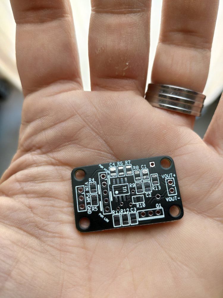
They are VERY small and very cute 
As soon as I get some spare time I will assemble the first one and perform some testing. If it all works ok, then I will move it to the betatesters phase 
Boards arrived!

They are VERY small and very cute 
As soon as I get some spare time I will assemble the first one and perform some testing. If it all works ok, then I will move it to the betatesters phase 
First batch ordered!
15 PCB are on its way 
If there is no problem with the design, I'll order about 50 more, wich would be enough for all the boards everyone asked for.
Anyone wants to betatest a board from this first batch once arrives?
@egon-net said in Designing a PWM to Analog mini board for fans:
25 board batch on its way!
- Parts ordered to Mouser
- Boards ordered to JLCPCB


Waiting...
@egon-net said in Designing a PWM to Analog mini board for fans:
@egon-net said in Designing a PWM to Analog mini board for fans:
25 board batch on its way!
- Parts ordered to Mouser
- Boards ordered to JLCPCB
- Parts arrived from Mouser
- Boards in their way from JLCPCB
Waiting...

It all seems ok, so I will build the boards and send them as soon as posible 
First board assembled and tested!

You can see the new integrated electrolytic capacitor, smd diode and led. I'll try to assemble/pack all boards this weekend, and send them early next week.
All the boards have been sent!
Please message me with an email so I can send the board documentation to everyone.
I have the very same problem! And I also have a toolchanger just like you, custom CoreXY motion system with e3d toolchanger hardware. The thing is my bed is almost flat and it doesn't make my prints fail, but I no longer have the perfect first layers I used to have since I went toolchanging. I even thought that the extra weight of the tool was making my X gantry sag, but the expected sagging doesn't quite match the effect I see when printing.
@bananapuppy said in PWM to constant DC voltage for fan control:
SA105E104MARTB AVX
Ceramic is ok, but I'd try to get one with X5R or X7R dielectric. The one you picked has Z5U dielectric which is not that good.
Europe -> Spain -> Valencia
I am in the very same situation. Same kind of machine, but just one Z motor moving two ballscrews.
@tpra said in Wavy surface problem.:
@egon-net same quality at low speed. even better actually.
if i don't go faster with rrf it's because it produces too much ghosting but that's another story
anyway klipper produces the same quality from 40 to 130.
Can you test Klipper without input shaper? I wonder how much of the quality increase is beacuse of it...
Nice!
This weekend I will update the post with schematics and simulations, and wait to see if more people are interested. If I have enough time I'll build a protoboard version and measure it with an oscilloscope and share it too.
And please leave a way to do it for the good old Duet 2 Wifi 
@dc42 said in RRF 3.4 input shaping preview available:
@jenpet said in RRF 3.4 input shaping preview available:
@dc42 the two contour lines get thinner and thinner at the end so that there is a gap between them.
Now I try to lower PA value again.If you mean the two perimeter lines, they are joined in the perimeter at the top, joined for part of the length of the perimeter on the right, and not joined at all in the perimeter at the bottom. The difference between top and bottom suggests to me that you have chosen an unfortunate wall thickness and the slicer has failed to ensure consistent infill by altering the extrusion widths - so that whether the perimeters are joined or not is very sensitive to small changes. I am assuming that the thickness of all three walls is supposed to be the same.
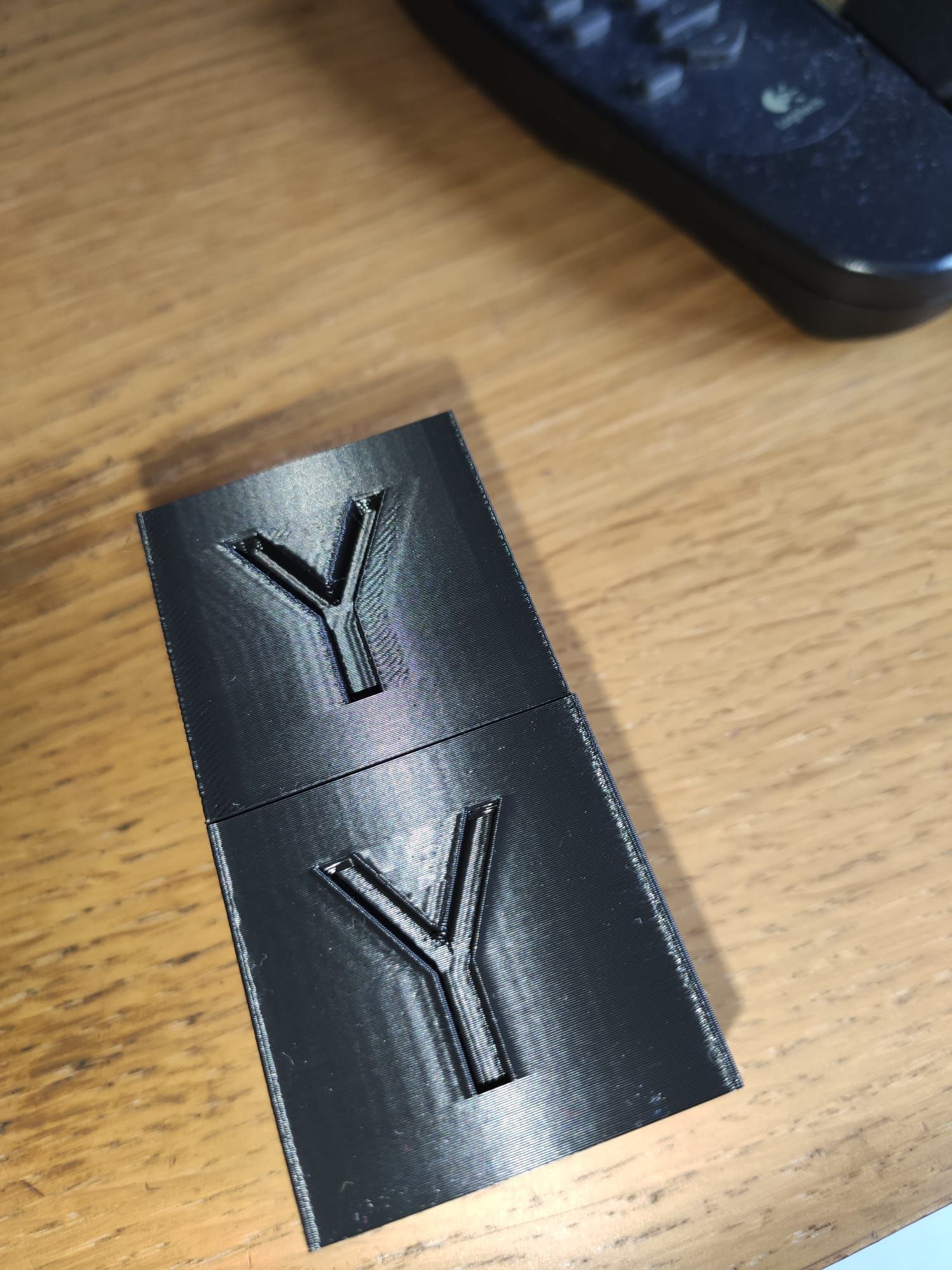
I also have problems with pressure advance and input shaping with de PA values I already got finetuned without input shaping.
Top one: input shapping ei3 @48Hz + PA 0.1 (orbiter extruder direct)
Bottom one: just input shapping and no PA
Both 100mm/sec, 6000mm/s2 acceleration
You can see corners are ok with the PA, and bulges with no PA...
Hello all!
I'm building a custom toolchanger with e3d toolhead and toolplates, and I was having problems with fans not reacting to PWM or being very whinny/loud/weak as soon as I PWM'd them, so I'm designing a very simple circuit with an low pass configured opamp and a transistor that should give a nice and stable analog voltage from the PWM signal from the duet.
Since I'm lowpass filtering in small signal, no inductors are needed, just a couple of resistors and capacitors, EMI should not be a problem, and the pcb should be very small.
My aim is just to use an all 24V system, but it would be rather easy to make the circuit voltage-agnostic so you could be able to mix and match fan voltages in the future.
Is anyone interested in such a circuit? I'm thinking about having some pcb boards manufactured, and since most services are about 20 pieces minimum order, I will have plenty of them...
Any thoughts?
@fcwilt said in Designing a PWM to Analog mini board for fans:
@Egon-Net said in Designing a PWM to Analog mini board for fans:
That's the very reason I'm doing all of this: I'm driving 6 fans from a Duex 5 board, and I already calculated that the inductor for a LC filter would be huge, and I'd need 6 of them. That's why I went with this route. But thanks for the advice!
Have you determined what it is about your fans that cause them to not work with PWM?
I have dozens of different kinds of brushless fans from many different vendors and they all work fine with PWM.
Thanks.
Frederick
Yes, I've done quite a lot of test. Some of my fans don't work at all as soon as you drop from 99% PWM. Most of them work, but PWM is not linear at all: 99% is already less than 25% airflow, and 50% PWM is no much less than that, and some of them kinda work with PWM, but whinning an awful lot, since they are connected to a Duex5 and I cannot change PWM frequency at all.
I suppose that 4010 fans, and even more, 4010 brushless radial fans are very tricky to get working with PWM.
By contrast, using my bench power supply, all of them work more or less linearly, at the very least from 12V to 24V.
In my other old printer (an old cartesian Marlin based custom one) I'm using 4020 and 5015 radial fans and managed to get some fans that work ok with PWM.
@fcwilt said in Designing a PWM to Analog mini board for fans:
@Egon-Net said in Designing a PWM to Analog mini board for fans:
Yes, I've done quite a lot of test. Some of my fans don't work at all as soon as you drop from 99% PWM. Most of them work, but PWM is not linear at all: 99% is already less than 25% airflow
That doesn't make sense.
According to my oscilloscope 100% is pure DC and 99% is 99% "pure DC".
It seems strange that those 1% intervals where the power to the fan drops to 0 would reduce the airflow to 25%.
Weird.
Frederick
As @zapta said, brushless motors are driven by embedded electronics, they are not just inductors and magnets. And some electronics are very susceptible to supply anomalies. If you do something like this to an opamp, it will easily begin to oscilate. The 99% "pure DC" has 250 narrow gnd peaks per second, which generates infinite harmonics that can and indeed disturb most electronics. If you have an original e3d V6, try to PWM its 24V 3010 fan. It will stop as soon as PWM is activated, no matter the %. And if you have a 24V 4010 radial fan from TriangleLabs (if they have not changed the source) try to PWM it, and witness the speed fall once you go to a non-100% PWM.
@taconite said in Designing a PWM to Analog mini board for fans:
@Egon-Net
mhh thats a bummer. I wanted to do 12V PWM to 5 V analog.
But as it seems you are a specialist in electronics. Do you have an idea why this simple optocoupler didn't work for that purpose:
https://forum.duet3d.com/topic/19325/powering-arduino-nano-and-leds-from-5v-rail/12
Do you realize you could just use the PWM- from duet and 5V instead of Duet's Fan Vcc? You are not forced to use 24V/12V from Duet.
Here you have a example just with passive components:
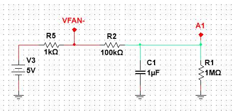
Since your load is Arduino's analog input, and assuming it has quite a high input impendance (IIRC, 1MOhm) you could just pull-up with your 5V supply with a 1K resistor (5mA current draw) and use VFan- from Duet (which is a PWM open drain). You'll have a little offset from de resistive divisor around A1, but it would be small. According my simulations, 2.3V for 50% PWM, 0V for 0% PWM and 4.54V por 100% PWM. You can play with R2 and C1 values a bit more to achieve even better results (for example 10k-10u).
Of course you could also use my board, but I think your problem doesn't need it.
@zapta said in Designing a PWM to Analog mini board for fans:
@Egon-Net said in Designing a PWM to Analog mini board for fans:
Comments?
Looks great and cute
A few random thoughts, please take with a grain of salt.
- Are the components at the back of the board optional?
No, just the led and its resistor are optional
- It seems that the new layout considerably restricted the ground path from the GND input to the transistor. I don't know if it matters or not.
There's a dual GND plane, top and bottom are GND. Plenty of copper for GND 
- Is there sufficient clearance for a spacer wall at the bottom, at the screw hole near the diode? Hard to see from the pictures here.
A real diode is not as huge as in the render, so there should be no problem. Just in case, I was going to print the PCB in paper and check the clearances for every hole. We could also use a SMD diode, but I have a lot of 1N4001 at home, that's why I picked it.
- You may want to add voltage input specification on the top of bottom silk screen. e.g. 12V - 24V or whatever the range is.
Good idea. It should be good for 4.5V-40V (But the hight the voltage, the lower the usable current due to power dissipation)
- I think that VCC typically means +5V. Maybe change to Vin+
Mmm VCC for me means "any positive voltage", but I can rename it to Vin+ if it seems clearer.
- The PWM input is active low. That is, if ones measure 10% high, it means 90% PWM value. I wonder if it can be conveyed somehow on the board to avoid confusion.
PWM is active low, but I configured the comparator opamp to do inversion, so it follows the PWM percentage. It will be active low when using PWM voltage.
Looking at the responses here, it seems to be a great ideas that will benefit many.
I'm very glad!
Well, I think I have the final design:
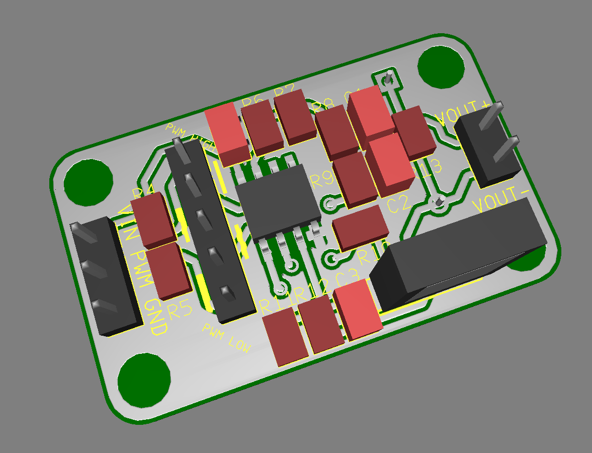
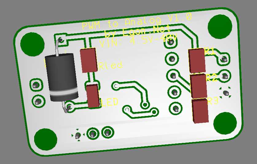
Besides minor cosmetic changes, I've added a jumper column to select PWM active high or active low with two jumpers. You can put the pins and jumpers or just solder it fixed. The silkscreen guides you about which ones to short por PWM active HIGH or PWM active LOW. PCB now is a bit bigger, but I think is worth it.
Any comments before I launch the order?