Haven't used my RRF printer in a few months due to it not printing as well as the Qidi. I saw this post and decided to dust off the Jubilee and load up 3.6 alpha and give it a go. I only have a few prints in but see a big improvement in print quality over the 3.5 version it replaced. So far not having an issues but have only used a single tool. Will try to do a multi color this weekend.
Best posts made by edsped
-
RE: RepRapFirmware 3.6.0-alpha.2 for Duet main boards available
-
RE: Duet3D announces new tool board at FormNext
@Surgikill said in Duet3D announces new tool board at FormNext:
@fcwilt said in Duet3D announces new tool board at FormNext:
@Herve_Smith
You consider the prices to be an issue?
The money I spend on hardware is dwarfed by the money I spend on filament.
Frederick
Toolboards are primarily made for tool changer setups, so multiply your cost difference by the number of toolheads. I'm currently building a tool changer, and each toolhead is going to run me close to $400. At some point, cost becomes a favor. When my toolhead alone is over double the cost of an ender 3 you have to take a step back and reevaluate.
I run RRF-36's on my toolchanger and wish I set it up that way sooner.
-
RE: Fly-RRF-36 RP2040 Based CAN-FD Toolboard
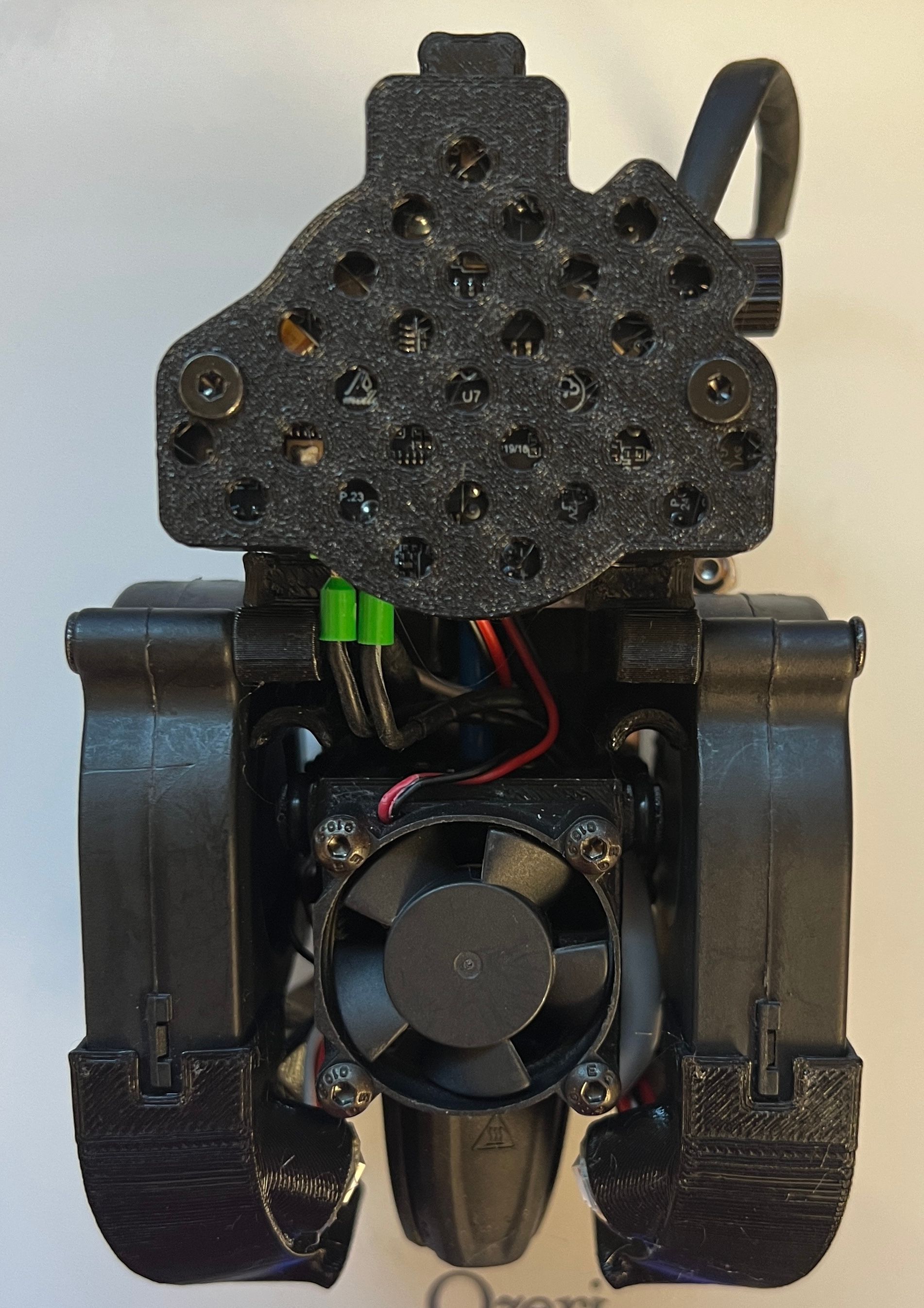
Have (4) paired with a Duet 3 6hc running on a toolchanger. I’m a little worried about heat with the board being covered but a o far no real issues and on board temps stay under 60C. My cover is as follows…
-
RE: 3.5.0rc1 Input Shaping Layer Shifts not addressed in 3.5.0rc2
@edsped I'll try lowering the L value to the default .25 and test again but it may take a couple of hours.
-
RE: Fly-RRF-36 RP2040 Based CAN-FD Toolboard
As an aside, I pulled the cover off after a 2 1/2 hour print last night and did the finger test for temps and nothing was above luke warm. I know it's not very scientific but it helped with some of my heat concerns.
-
RE: Z-axis / tramming issues with 3.6.0-alpha2+3
Been printing on and off for several prints and knock on wood haven't had any tramming issues. Print quality is also very much improved over 3.52. Looking forward to further improvements.
-
RE: Software bundle 3.6.0-beta.1 now available
A few prints in and it seems as if adding the M400 to cancel.g addressed the issue. I guess I haven't been cancelling prints on the alpha.. Otherwise all seems to be working as expected.
Latest posts made by edsped
-
RE: Software bundle 3.6.0-beta.1 now available
A few prints in and it seems as if adding the M400 to cancel.g addressed the issue. I guess I haven't been cancelling prints on the alpha.. Otherwise all seems to be working as expected.
-
RE: Software bundle 3.6.0-beta.1 now available
I didn't have an M400 command after the tool park in my cancel.g file so that may be the culprit. I'll add it and retry but it won't be until tomorrow.
-
RE: Software bundle 3.6.0-beta.1 now available
@dc42 I'm not sure what's changed between the last alpha and the current beta but the Jubilee is once again dropping tools even with the M400's...
edit: on a side note it primarily appears to happen after I cancel a print and it parks the tool. At this point I'm reverting to the alpha 5 as it's been pretty solid.
-
RE: RepRapFirmware 3.6.0-alpha.4+3 available for testing
Day 3 without any tool drops so I'm going to say inserting M400 prior to tool lock/unlock macros is working. Out of curiosity, will this be addressed in the final release or will the M400 always be required? It won't matter much for me as I'll likely forget to remove it when the 3.6 is released but I am curious.
-
RE: RepRapFirmware 3.6.0-alpha.4+3 available for testing
A quickie follow up, several prints, maybe 50'ish tool changes and no issues. It appears as if the M400 is helping.
-
RE: RepRapFirmware 3.6.0-alpha.4+3 available for testing
Will try the M400 commands and if they don't help, I'll disable IS at start of tool change and re-enable it after tool is picked up.
Thanks for the assistance
-
RE: RepRapFirmware 3.6.0-alpha.4+3 available for testing
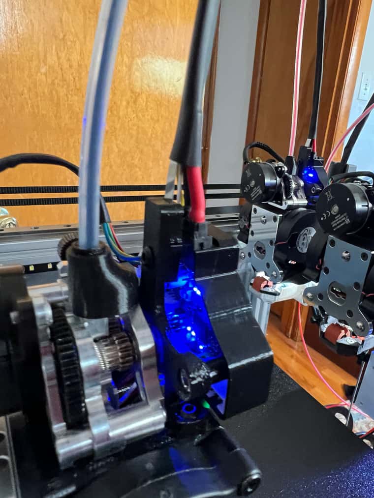
@dc42 I added M400 prior to macro calls for lock and unlock and stuck one in the macro as well... Following are the macros if that helps and a couple of pictures showing the pin when a failure occurs.. Pin should be horizontal when unlocked and stop should be at the limit switch, when there's a tool drop the stepper never reaches the limit switch...
tool_lock.g
; Engage the toolchanger lock. RepRap Firmware V2.0.1 version. G91 ; Set relative mode G1 U10 F5000 H0 ; Back off the limit switch with a small move M400 G1 U200 F5000 H1 ; Perform up to one rotation looking for the torque limit switch ;G1 U200 Y0.5 F5000 H1 ; Perform up to one rotation looking for the torque limit switch G90 ; Set absolute mode
tool_unlock.g
; Disengage the toolchanger lock G91 ; Set relative movements G1 U-4 F9000 H2 ; Back off the limit switch with a small move M400 G1 U-360 F9000 H1 ; Perform up to one rotation looking for the home limit switch G90 ; Restore absolute movements
-
RE: RepRapFirmware 3.6.0-alpha.4+3 available for testing
@dc42 One thing that is consistent when there's a tool drop is that the locking pin isn't fully rotated to the lock or unlock position which initially had me thinking there was mechanical binding. I'll stick an M400 before the call to the tool lock/unlock macro to see if that helps. I've reduced my tool change speeds by about 60% to see if that helped and it made no difference, but I'll leave them low until I figure out why I'm not getting proper tool engagement.
-
RE: RepRapFirmware 3.6.0-alpha.4+3 available for testing
@o_lampe I've lowered tool change speeds to see if that helped and it didn't. Initially my rationale for high speeds was to minimize ooze in an effort to eliminate the need for a wipe tower. It didn't work and I never lowered them but have more than halved them the past few days...
-
RE: RepRapFirmware 3.6.0-alpha.4+3 available for testing
@gloomyandy Follow up several prints and a couple of hundred tool changes on 3.5.1, reverted to the latest 3.6.0 A5, (2) prints in and a tool is dropped while pulling away from the parking post. Config.g below
; Jubilee CoreXY ToolChanging Printer - Config File ; This file intended for Duet 3 hardware, main board plus Tool Boards ; Name and network ; This is configured from the connected Raspberry Pi or here if in stand alone ; mode ; Connect to PanelDue 7i M575 P1 S0 B57600 ;------------------------NETWORKING IF NOT HANDLED BY SBC------------------------------ ; Networking ;M540 PBE:43:37:31:51:31 M550 P"Jubilee" ; Name used in ui and for mDNS http://Jubilee.local M552 P0.0.0.0 S1 ; configure Ethernet adapter M586 P0 S1 ; configure HTTP ;M552 S1 P192.168.1.19 ; Use Ethernet with a static IP, 0.0.0.0 for dhcp ;M553 P255.255.255.0 ; Netmask ;M554 192.168.1.1 ; Gateway ; General setup ;------------------------------------------------------------------------------- M550 P"Printster" ; Set Machine Name G4 S2 ; Pause for 2 seconds to allow CAN boards to initiate M111 S0 ; Debug off M929 P"eventlog.txt" S0 ; Start logging to file eventlog.txt (turned logging off) ; General Preferences M555 P2 ; Set Marlin-style output G21 ; Set dimensions to millimetres G90 ; Send absolute coordinates... M83 ; ...but relative extruder moves ; Stepper mapping ;------------------------------------------------------------------------------- ; Connected to the MB6HC as the table below. ; Note: first row is numbered left to right and second row right to left ; _________________________________ ; | X(Right) | Y(Left) | U(lock) | ; | Z(Back) | Z(Right) | Z(Left) | M584 X0 Y1 ; X and Y for CoreXY M584 U2 ; U for toolchanger lock M584 Z3:4:5 ; Z has three drivers for kinematic bed suspension. ;*********************RRF-36 Stepper Mapping ****************************************** M584 E20.0:21.0:22.0:23.0 ; "AMY" "BETTY" "CHLOE" "DAISY" Extruder drive mapping M569 P0 S0 ; Drive 0 | X stepper M569 P1 S0 ; Drive 1 | Y Stepper M906 X{0.6*sqrt(2)*2500} ; LDO XY 2500mA RMS the TMC5160 driver on duet3 M906 Y{0.6*sqrt(2)*2500} ; generates a sinusoidal coil current so we can ; multply by sqrt(2) to get peak used for M906 ; Do not exceed 90% without heatsinking the XY ; steppers. M569 P2 S0 ; Drive 2 | U Tool Changer Lock 670mA M906 U{0.7*sqrt(2)*670} I60 ; 70% of 670mA RMS idle 60% ; Note that the idle will be shared for all drivers M569 P3 S0 ; Drive 3 | Front Left Z M569 P4 S0 ; Drive 4 | Front Right Z M569 P5 S0 ; Drive 5 | Back Z M906 Z{0.6*sqrt(2)*2500} ; 70% of 2500mA RMS ;********************RRF-36 Tool steppers on expansion board**************************** M569 P20.0 S0 D2 ; Drive 0 "AMY" direction | Extruder 0 in Spreadcycle Mode M569 P21.0 S0 D2 ; Drive 1 "BETTY" direction | Extruder 1 in Spreadcycle Mode M569 P22.0 S0 D2 ; Drive 2 "CHLOE" direction | Extruder 2 in Spreadcycle Mode M569 P23.0 S0 D2 ; Drive 3 "DAISY" direction | Extruder 3 in Spreadcycle Mode ;======================SET MAXIMUM PRINTING SPEEDS============================================ M204 P5000 T5000 ; Kinematics ;------------------------------------------------------------------------------- M669 K1 ; CoreXY mode ; Kinematic bed ball locations. ; Locations are extracted from CAD model assuming lower left build plate corner ; is (0, 0) on a 305x305mm plate. M671 X297.5:2.5:150 Y313.5:313.5:-16.5 S10 ; Front Left: (297.5, 313.5) ; Front Right: (2.5, 313.5) ; Back: (150, -16.5) ; Up to 10mm correction ; Axis and motor configuration ;------------------------------------------------------------------------------- M350 X1 Y1 Z1 U1 ; Disable microstepping to simplify calculations M92 X{1/(0.9*16/180)} ; step angle * tooth count / 180 M92 Y{1/(0.9*16/180)} ; The 2mm tooth spacing cancel out with diam to radius M92 Z{360/0.9/4} ; 0.9 deg stepper / lead (4mm) of screw M92 U{13.76/1.8} ; gear ration / step angle for tool lock geared motor. ; Enable microstepping all step per unit will be multiplied by the new step def M350 X32 Y32 I1 ; 16x microstepping for CoreXY axes. Use interpolation. M350 U4 I1 ; 4x for toolchanger lock. Use interpolation. M350 Z16 I1 ; 16x microstepping for Z axes. Use interpolation. M350 E16 I1 ; 16x microstepping for Extruder axes. Use interpolation. ; Speed and acceleration ;------------------------------------------------------------------------------- M201 X8000 Y8000 ; Accelerations (mm/s^2) M201 Z100 ; LDO ZZZ Acceleration M201 U800 ; LDO U Accelerations (mm/s^2) M203 X24000 Y24000 Z800 U9000 ; Maximum axis speeds (mm/min) M566 X2000 Y2000 Z100 U50 P1 ; Maximum jerk speeds (mm/min) ;********************RRF-36 motor configuration *************************************** M906 E800:800:800:800 I10 ; Motor currents for all E (mA). M201 E18000:18000:18000:18000 ; E600:600:600 E Acceleration (mm/s^2) M203 E7200:7200:7200:7200 ; Maximum axis speeds (mm/min) was 3600 M566 E3000:3000:3000:3000 ; Maximum jerk speeds (mm/min) M92 E719:719:719:719 ;E Steps VZ-Hextrudort - 0.9 deg/step Tool0:Tool1:Tool3 ; Endstops and probes ;------------------------------------------------------------------------------- ; Connected to the MB6HC as the table below. ; | U | Z | ; | X | ; | Y | M574 U1 S1 P"^io4.in" ; homing position U1 = low-end, type S1 = switch M574 X1 S1 P"^io1.in" ; homing position X1 = low-end, type S1 = switch M574 Y1 S1 P"^io2.in" ; homing position Y1 = low-end, type S1 = switch M574 Z0 ; we will use the switch as a Z probe not endstop M558 P8 C"io3.in" H3 F360 T6000 ; H = dive height F probe speed T travel speed G31 K0 X0 Y0 Z-2 ; Set the limit switch position as the "Control Point." ; Note: the switch free (unclicked) position is 7.2mm, ; but the operating position (clicked) is 6.4 +/- 0.2mm. ; A 1mm offset (i.e: 7.2-6.2 = 1mm) would be the ; Z to worst-case free position, but we add an extra 1mm ; such that XY travel moves across the bed when z=0 ; do *not* scrape or shear the limit switch. ; Set axis software limits and min/max switch-triggering positions. ; Adjusted such that (0,0) lies at the lower left corner of a 300x300mm square ; in the 305mmx305mm build plate. M208 X-13.75:313.75 Y-44:341 Z0:295 M208 U0:200 ; Set Elastic Lock (U axis) max rotation angle ; Heaters and temperature sensors ;---------------------------------------------------------------------------------------------------- ; Bed M308 S0 P"temp0" Y"thermistor" T100000 B3950 A"Bed" ; Keenovo thermistor M950 H0 C"out0" T0 ; H = Heater 0 ; C is output for heater itself ; T = Temperature sensor M143 H0 S130 ; Set maximum temperature for bed to 130C M307 H0 A589.8 C589.8 D2.2 V24.1 B0 ; Keenovo 750w 230v built in thermistor ; mandala rose bed M140 H0 ; Assign H0 to the bed ;**********************FLY-RRF 36 Extruder configurations********************************************** ;---------------------Tool 0 aka "AMY" With CAN Address 20.0 ------------------------------------------ ;Heater Thermistor M308 S1 P"20.TEMP0" Y"thermistor" T100000 B4725 C7.06e-8 A"Amy" ;"T1" Semtec Thermistor defined ;M308 S6 P"20.temp1" Y"thermistor" A"Amy Fly RRF" T100000 B4092 ; Cooling Fans M950 F0 C"20.out1" ; Fan 0, part cooler fan on Tool 0 M106 P0 C"Amy" ; Set Fan Name M950 F1 C"20.out2" ; Fan 1, hotend fan on Tool 0 M950 H1 C"20.out0" T1 ; Heater 1 "H1" uses the Out0 pin and Temp0 M570 H1 P15 T20 R5 ; An anomaly on "H1" must persist for 15 seconds, and must be greater or less than 20C from the setpoint, to raise a heater fault. M143 H1 S280 ; Maximum H1 (Extruder 1) heater temperature M106 P1 S1.0 T45 H1 ; Tool 0 Hotend Fan to start cooling at 45C Monitoring Heater 1 (H1) M563 P0 S"Amy" D0 H1 F0 ; Define tool 0 "AMY" using H1 heater, F0 cooling ;G10 P0 X0.188 Y32.637 Z-0.345 ; Set tool 0 offset from the bed FOR INITIAL SETUP ONLY SEE VALUES IN CONFIG OVERRIDE G10 P0 S0 R0 ; Set tool 1 operating (S) and standby temperatures (R) (-273 = "off") M572 D0 S0.04 ; Set pressure advance on Extruder Drive 1 ;Turn on tool Lights M950 E0 C"20.rgbled" T2 U2 ; Strip number, Pin ID, type, Max # of LED'S ;M150 E0 U0 R0 B0 W255 S1 F1 P255 ; for RGBW LED Only ;M150 E0 U0 R0 B0 W255 S1 F0 P255 ; for RGBW LED Only M955 P20.0 I52 ; Enable accelerometer on Amy ;---------------------End of Tool 0 aka "AMY" ----------------------------------------------------------- ;---------------------Tool aka "BETTY" With CAN Address 21.0 ------------------------------------------ ;Heater Thermistor M308 S2 P"21.TEMP0" Y"thermistor" T100000 B4725 C7.06e-8 A"Betty" ;"T1" Semtec Thermistor defined ;M308 S7 P"21.temp1" Y"thermistor" A"Betty Fly RRF" T100000 B4092 ; Cooling Fans M950 F2 C"21.out1" ; Fan 2, part cooler fan on Tool 1 M106 P2 C"Betty" ; Set Fan Name M950 F3 C"21.out2" ; Fan 3, hotend fan on Tool 1 M950 H2 C"21.out0" T2 ; Heater 2 "H2" uses the Out0 pin and Temp0 M570 H2 P15 T20 R5 ; An anomaly on "H2" must persist for 15 seconds, and must be greater or less than 20C from the setpoint, to raise a heater fault. M143 H2 S280 ; Maximum H2 (Extruder 1) heater temperature M106 P3 S1.0 T45 H2 ; Tool 1 Hotend Fan to start cooling at 45C Monitoring Heater 2 (H2) M563 P1 S"Betty" D1 H2 F2 ; Define tool 1 "BETTY" using H2 heater, F2 cooling ;G10 P1 X0.188 Y32.637 Z-0.345 ; Set tool 1 offset from the bed FOR INITIAL SETUP ONLY SEE VALUES IN CONFIG OVERRIDE G10 P1 S0 R0 ; Set tool 1 operating (S) and standby temperatures (R) (-273 = "off") M572 D1 S0.04 ; Set pressure advance on Extruder Drive 2 ;Turn on tool Lights M950 E1 C"21.rgbled" T2 U2 ; Strip number, Pin ID, type, Max # of LED'S ;M150 E1 U0 R0 B0 W255 S1 F1 P255 ; for RGBW LED Only ;M150 E1 U0 R0 B0 W255 S1 F0 P255 ; for RGBW LED Only M955 P21.0 I52 ; Enable accelerometer on Betty ;-------------------------------End of Tool 0 aka "BETTY". ------------------------------------- ;---------------------Tool aka "CHLOE" With CAN Address 22.0 ------------------------------------------ ;Heater Thermistor M308 S3 P"22.TEMP0" Y"thermistor" T100000 B4725 C7.06e-8 A"Chloe" ;"T1" Semtec Thermistor defined ;M308 S8 P"22.temp1" Y"thermistor" A"Chloe Fly RRF" T100000 B4092 ; Cooling Fans M950 F4 C"22.out1" ; Fan4, part cooler fan on Tool 2 M106 P4 C"Chloe" ; Set Fan Name M950 F5 C"22.out2" ; Fan 5, hotend fan on Tool 2 M950 H3 C"22.out0" T3 ; Heater 3 "H3" uses the Out0 pin and Temp0 M570 H3 P15 T20 R5 ; An anomaly on "H3" must persist for 15 seconds, and must be greater or less than 20C from the setpoint, to raise a heater fault. M143 H3 S280 ; Maximum H3 (Extruder 2) heater temperature M106 P5 S1.0 T45 H3 ; Tool 3 Hotend Fan to start cooling at 45C Monitoring Heater 3 (H3) M563 P2 S"Chloe" D2 H3 F4 ; Define tool 2 "CHLOE" using H3 heater, F4 cooling ;G10 P2 X0.188 Y32.637 Z-0.345 ; Set tool 1 offset from the bed FOR INITIAL SETUP ONLY SEE VALUES IN CONFIG OVERRIDE G10 P2 S0 R0 ; Set tool 1 operating (S) and standby temperatures (R) (-273 = "off") M572 D2 S0.04 ; Set pressure advance on Extruder Drive 2 ;Turn on tool Lights M950 E2 C"22.rgbled" T2 U2 ; Strip number, Pin ID, type, Max # of LED'S ;M150 E2 U0 R0 B0 W255 S1 F1 P255 ; for RGBW LED Only ;M150 E2 U0 R0 B0 W255 S1 F0 P255 ; for RGBW LED Only M955 P22.0 I52 ; Enable accelerometer on CHLOE ;-------------------------------End of Tool 0 aka "CHLOE". ------------------------------------- ;---------------------Tool aka "DAISY" With CAN Address 22.0 ------------------------------------------ ;Heater Thermistor M308 S4 P"23.TEMP0" Y"thermistor" T100000 B4725 C7.06e-8 A"Daisy" ;"T3" Semtec Thermistor defined ;M308 S9 P"23.temp1" Y"thermistor" A"Daisy Fly RRF" T100000 B4092 ; Cooling Fans M950 F6 C"23.out1" ; Fan4, part cooler fan on Tool 3 M106 P6 C"Daisy" ; Set Fan Name M950 F7 C"23.out2" ; Fan 7, hotend fan on Tool 4 M950 H4 C"23.out0" T4 ; Heater 4 "H4" uses the Out0 pin and Temp0 M570 H4 P15 T20 R5 ; An anomaly on "H4" must persist for 15 seconds, and must be greater or less than 20C from the setpoint, to raise a heater fault. M143 H4 S280 ; Maximum H4 (Extruder 2) heater temperature M106 P7 S1.0 T45 H4 ; Tool 4 Hotend Fan to start cooling at 45C Monitoring Heater 4 (H4) M563 P3 S"Daisy" D3 H4 F6 ; Define tool 4 "DAISY" using H4 heater, F4 cooling ;G10 P3 X0.188 Y32.637 Z-0.345 ; Set tool 4 offset from the bed FOR INITIAL SETUP ONLY SEE VALUES IN CONFIG OVERRIDE G10 P3 S0 R0 ; Set tool 4 operating (S) and standby temperatures (R) (-273 = "off") M572 D3 S0.04 ; Set pressure advance on Extruder Drive 4 ;Turn on tool Lights M950 E3 C"23.rgbled" T2 U2 ; Strip number, Pin ID, type, Max # of LED'S ;M150 E3 U0 R0 B0 W255 S1 F1 P255 ; for RGBW LED Only ;M150 E3 U0 R0 B0 W255 S1 F0 P255 ; for RGBW LED Only M955 P23.0 I52 ; Enable accelerometer on DAISY ;-------------------------------End of Tool 0 aka "DAISY". ------------------------------------- ;*******************************END OF RRF-36 TOOLS ********************************************** M593 P"ZVD" F55 L0.25 S0.1 ; Set Dynamic Acceleration Adjustment M376 H10 ; bed compensation taper M98 P"config-user.g" ; Load custom user config M501 ; Load saved parameters from non-volatile memory