Yes apologies I forgot to answer that. I am using PrusaSlicer v2.3 on Linux. But I also experienced the same issue with Windows when I was on RRF2.05.
Posts made by Dkos
-
RE: PrusaSlicer DWC disconnect on upload/test.posted in Duet Web Control
-
RE: PrusaSlicer DWC disconnect on upload/test.posted in Duet Web Control
Thank you both for the replies. I just updated to DWC 3.2. Almost good news.
I do not entirely lose connection. Meaning it gets a connection interrupt, but it reconnects automatically. No need to re-enter password so thats good.
On the other hand something is still going wrong there, i get the following warning upon upload:
Connection interrupted, attempting to reconnect...
JSON.parse: unexpected character at line 1 column 1 of the JSON data
But updating indeed fixed the annoying part of the issue, thanks!
-
PrusaSlicer DWC disconnect on upload/test.posted in Duet Web Control
Hello, not sure if I should post this here or over the PrusaSlicer support, but I am giving it a shot in case anyone else has experience something similar since I cant seem to find anything related on the web.
The subject is pretty much self-explanatory, every time I upload or test the connection from PrusaSlicer to the DWC I lose connection. Then I have to refresh, re-enter password and so on. It is annoying on the long run.. PrusaSlicer reports connection successful, and if I upload, the files are indeed uploaded, but then of course a disconnection follows.
This does not seem to be an issue when uploading from another slicer (e.g Cura).
System overview: Duet2Wifi on RRF3.2 with DWC 2.0.4 and Wifi server 1.25.
Has anyone experienced something similar?
-
RE: PID tuning with bed at different voltage.posted in Tuning and tweaking
So I deduct that the process of PID tuning itself (M303) is not affected but what voltage the Duet thinks the bed is on.
Nonetheless I did as suggested and disabled the psu voltage compensation. l am keeping the rest of the PID values as they are.
Thanks for the answers!
-
RE: PID tuning with bed at different voltage.posted in Tuning and tweaking
First thanks for the reply.
I would assume that you are referring to the M307 command which is the only one I can see to have a V parameter. I should have probably added the tuning command I used. Nonetheless this is it:
M303 H0 S110
M307 H0
M500
As far as I understand, in this scenario the M307 only reports the current settings, does not set new ones. A quick deduction would be that it automatically sets the voltage to the Duet running voltage level. If that is true I could do actually the opposite and manually set (in .config-override) the V parameter at 12V or removed it as proposed. But what would be the effect of this? M307 comes post-tuning, so as far as the PID tuning is concerned it would not matter whether the Duet correctly assumes the voltage of the bed?
-
PID tuning with bed at different voltage.posted in Tuning and tweaking
Hello people,
So, i finally found some time to play with the printer again and I made the switch from 12V to 24V system. Although, for budget reasons i decided to not buy (for now) a new heater for the bed. I am currently running the bed on a 12V 200W silicon heater. Therefore I kept my 12V psu and it is now dedicated for the bed heater (350W psu for a 200W heater but whatever..).
Now in the process of tuning everything to the new 24V i gave another shot at the PID tuning of the bed heater as well, but after the tuning is complete it is reported that the tuning voltage is at 24V instead of 12V that the bed is still running.
I would assume that the Duet does not know the actual voltage? (negative goes to Duet and positive goes directly into the 12V psu).
My question is, is this just an info printed by M307 H0 that i should not be worried about, or does it hint a mistake/problem?
Thanks in advance!
Edit: Board info: Duet 2 Wifi on firmware: 2.05 (I should probably update soon
 ).
). -
RE: Independted dual Z & Manual bed leveling assistant questionposted in General Discussion
@droftarts Thanks for sharing! It is nice to see an already working implementation. I will work on it (among some other things) over the weekend and will post back the results

-
RE: Independted dual Z & Manual bed leveling assistant questionposted in General Discussion
@dc42 Thanks for the detailed explanation! I think I understand what I have to do, it should be easy. I did not thought of providing two different M671 command chains in sequence.
You've given me an idea, which is to support auto levelling with 3 sets of coordinates and 2 motors, such that the firmware assumes that the 3rd coordinate is a manual screw and suggests a correction for it.
That was basically how I initially pictured it will work, would be great!
-
Independted dual Z & Manual bed leveling assistant questionposted in General Discussion
Hello everyone, I would not be surprised if the same question has been asked before, but I did not find an answer searching the forum so here it is:
Some background:
I followed this guide to set up my Dual independent Z:
https://duet3d.dozuki.com/Wiki/Bed_levelling_using_multiple_independent_Z_motorsBefore, I was quite fond of the Manual bed leveling assistant, and I used the config as explained here:
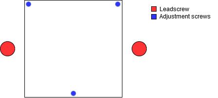
https://duet3d.dozuki.com/Wiki/Using_the_manual_bed_levelling_assistantNow the problem: when I was using the manual one, I had the 3 adjustment screws with the positions set via the M671 and I was probing as close as possible at each one of them. Then, I had the very nice console output on how much I should adjust each screw.
Converting to dual Z I had to change the M671 to define the position of each leadscrew. While that is perfect for the X axis (2 opposite leadscrews along that axis), and height difference is corrected by the motor automatically, this does not include the Y axis compensation.
As I understand, I can use the dual independent Z for X axis, and maybe the bed mesh compensation to account for the Y, but my question is:
Is it possible to define both the positions of the leadscrews and the adjustment screws differently, so i can get this nice console output while still using the dual Z.
I think of it like a sequence of probing close to the leadscrews -> motors adjusting ->probing close to adjustement screws->console output to adjust the screws. At the moment whenever I need to level the bed I am doing it by manually moving the head close the adjustment screws and checking the nozzle offset with a 0.1 feeler gauge.
Am i missing something?
P.S. I know from the theory that I need 3 points to define a plane, therefore I can have one point as reference and adjust the other 2 with the motors. For my system to work like this though, it will require mechanical changes that I can not implement at the moment.
-
RE: Bed minimum heating time.posted in Tuning and tweaking
@deckingman Followed your approach, and I second that it works much better. I drilled a 4mm deep hole with 2.5mm diameter and inserted the thermistor there, leaving 1mm before the top surface. Re-tuned the PID and I am very happy with the result.
Thanks for the tip!
-
RE: Print quality issueposted in Tuning and tweaking
@deckingman Yes, that is what i figured as well. Currently I switched to bolts with an unthreaded section while i am waiting for the order of shoulder-bolts with 5mm shoulder diameter. Rookie mistake from my side when I first assembled my printer.
-
RE: Print quality issueposted in Tuning and tweaking
@dc42 The way it was setup it had a bit more than a 1mm clearing between the part face and the bearing, something like this:

I tried a washer on the top as well, but it was always blocking at the end.The way i got a bit around that it was to use locknuts and fine tuning until i get the minimum play i could get while still allowing rotation. But i could not remove all the play no matter how much time i spend "fine-tuning" it..
Maybe it was just the batch of my idlers that were bad i dont know..
Edit: "badge" -> "batch"
-
RE: Print quality issueposted in Tuning and tweaking
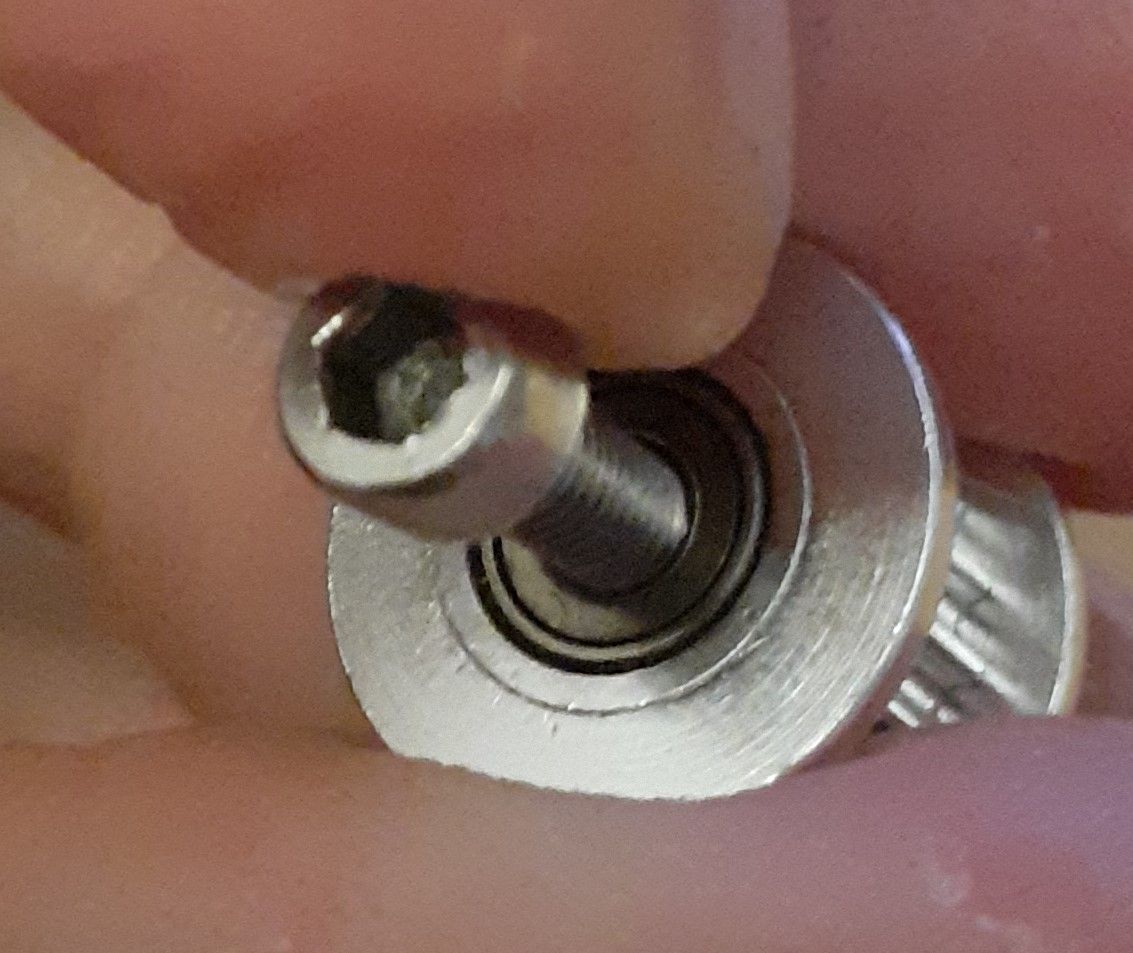
@OBELIKS This is as good of an image as i can get using my phone:

The small gap between the inner bore and the screw was enough to produce a fair amount of play (it is even visible that the screw is not completely perpendicular to the idler the way i am holding it).
The main problem is that I could not tighten up the screw as much as I should because the idler would not be turning anymore. This is no longer an issue using the flanged bearings. Moreover, even if I could screw it all the way, still I would never be sure that it will be totally concentric.
-
RE: Print quality issueposted in Tuning and tweaking
@Veti These are exactly the type i ordered as well, i am confident that the idlers will be much more robust.
-
RE: Print quality issueposted in Tuning and tweaking
Thanks!
@DocTrucker More and more things to keep track of! It may be a good idea to make a maintenance list with all the hardware to be checked in some "fixed" intervals..Now whether that will actually happen in the end or not is another matter

@OBELIKS I will try to see if I can capture it with my phone camera and I ll post back as soon as I get back in the evening!
-
RE: Print quality issueposted in Tuning and tweaking
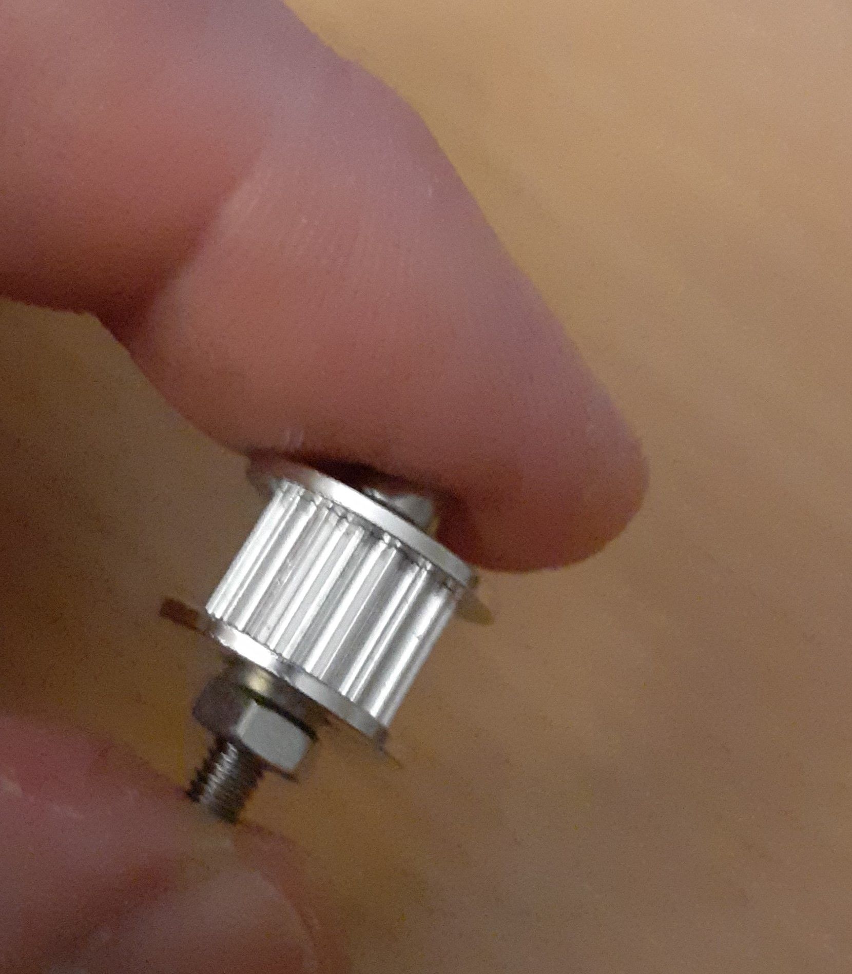
So, I finally solved my issue. The culprits where all these idlers:

These are the typical cheap ones, that had a fair amount of play between the inner 3mm bore and the m3 bolt which is of course less a bit less that 3mm. I did a quick test by replacing them with pairs of F623ZZ (which i was able to tighten all the way without blocking their rotation...) and had a huge quality improvement, so i went ahead and redesigned all the idlers to use F625ZZ to go from 3mm to 5mm shaft, and placed an order for shoulder bolts. That should be considerably stiffer.
That of course as far as the mechanical part is concerned. The slicer related issues might be compensated a fair amount by tweaking the settings, but not entirely disappear.
Thanks for all the ideas!
Edit: forgot to add some samples, not anything complicated but that only prints i have at the moment


-
RE: Coolmuscle servo motorsposted in General Discussion
For future reference.
We tested one of these motors with a Duet 2 Wifi board and it was successful. It is actually a closed loop stepper that accepts step/dir commands and the on-motor controller handles it from there, therefore the wiring and config was pretty straightforward.
Full conversion to Duet is on the way.
Cheers!
