Round 2 was a success!
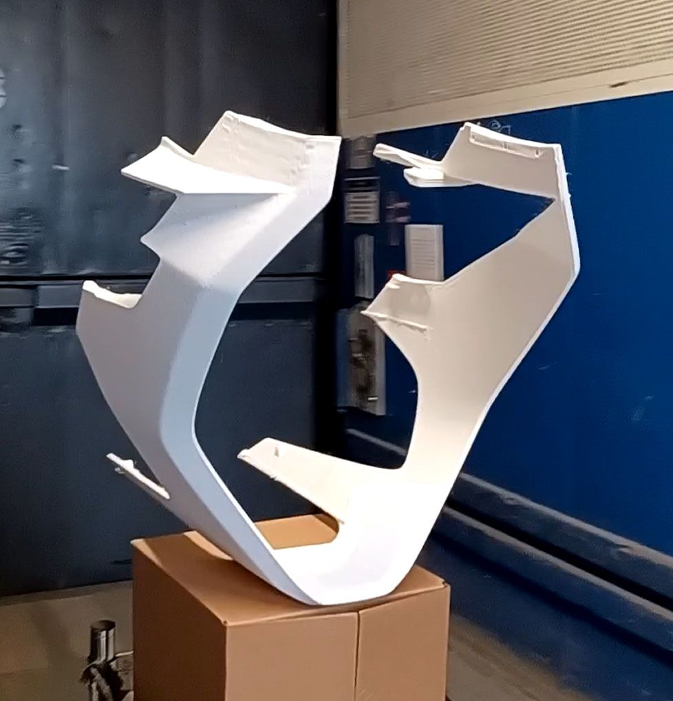
Or mostly a success. Definitely a usable part for initial track testing but the print does have some blemish areas.
I added Z hopping at 1mm so there was a ton of z motion going on but it did not affect the print time that much. The Z motor was a lot hotter. I may have to tune the retraction settings now as at some points it seemed to be depositing a tiny drop of material, z hopping to a couple mm away, and repeating for 30-50 times in a row. I am not getting any blobbing or stringing issues, so likely have some margin to reduce retractions.
The added z motion did accentuate the instability of really tall (500mm+) and slender support structures, as you could see them swaying back and forth a bit. Once the printhead was printing on them the motion was quickly damped, but it has a noticeable effect on surface print quality. I think the fast accelerations of the printer are causing problems when the center of mass of the printed plastic for an island is not over its center of support, so when I create these new CAD supports will try to either prevent that situation or try to give the added bracing some torsional stability. I found that adding 1 perimeter wall option to the support generation adds a lot of stability to the support islands, but it also greatly increases print time and support removal difficulty.

I think most browsers should play this video: https://www.instagram.com/p/CfKd1oqDCpV/
The part ran with a bunch of Cura generated supports around a bunch of 3 pass wide brace walls that were added to the CAD model in Creo. The uppermost horizontal walls were a bit wonky as a result of my added walls ending too soon and the Cura supports wobbling a bit. This wonkiness stopped when these islands were merged into the overall part perimeter, which was pretty stable due to the CAD added bracing.

So these parts are all good enough for initial assembly, dyno and track testing, but there will definitely be a round 2 once that all happens. When I do this part again (and actually for some other parts too), the supports will be revised to something like this:
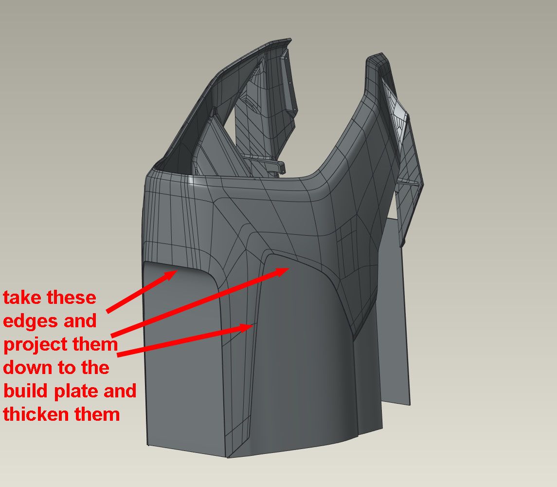
Basically, after orienting the part I will take the edges that are above the build plate, drape them down to intersect the build plate, then thicken them to 3 print passes. This will eliminate any isolated islands on the print bed and it will also convert the part from long, spindly and unstable fingers and supports to a stable closed profile with few supports. The rest of the fairing is about 5mm thick, and done with 2 walls and 10% gyroid infill. The result is that the added walls are 'solid' where they merge into the part so can be trimmed off without breaking through to the infill. The added part volume seems to be a decent amount less than the support structure it is replacing, and because they are usually long smooth print moves can be done at a consistent realized 150mm/sec, so also print decently faster than constantly reversing support movement.
I found that cutting these style ribs off was pretty easy with an oscillating handheld cutters (dremel mm35). No melting and with the right blade shape (standard one included in package) it was easy to get near flush cuts. No nicked fingers, either!
This last print was 52hrs. The printer has been going almost continually since 5/16 with no more than a few hours between prints. I've gone through about 28kg of filament so far. The only failure was the filament stepper fan, which burned out. Turns out it was a 12V fan running at 24V. I may add some shielding between the chamber heater elements and the build plate, as on the previous failed print it did seem that the heater on one side caused some of the single wall tree supports that were directly opposite it to sag. Other than that, the printer has been mechanically sound, which is great.
