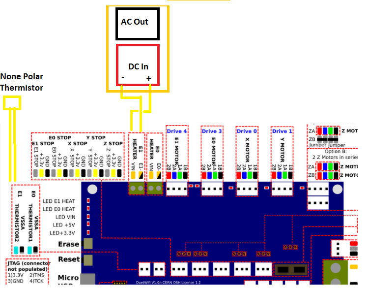
Voltage of heater 2 (E1) drops when enabled?
-
How have you connected the SSR input to the Duet?
-
Hi @dc42 yes I connected the Duet E1 Output to the SSR input ... I was measuring the DC Voltage from the SSR Terminals.
Yes the voltage polarity was correct.
Is there surge protection on the E1 Circuitry ?
I would have thought that the 10KOhm resister on the SSR would be sufficient load for the Duet.
What I find strange is that the voltage drops when I set a temperature for the enclosure.
The trigger voltage for the SSR is 3v.
-
@simonboydfoley said in Voltage of heater 2 (E1) drops when enabled?:
Hi @dc42 yes I connected the Duet E1 Output to the SSR input
That doesn't answer my question. How exactly have you connected the two SSR input terminals?
-
apologies @dc42 ive been at an offsite, thought the reply made sense ... but attached is an ugly diagram of the connections I have used and their polarity.
I have a replacement SSR Turning up tomorrow,Does this answer your question ?
The cable is AWG 18
-
How does the E1 heat LED on the Duet behave when you do these tests?
To turn the chamber heater on at full PWM, you will probably need to set a temperature much higher than 30C, at least until you have tuned the chamber heater.
The 19mV reading is probably caused by the LEDs generating a small amount of power from ambient light.
-
@dc42 Problem with the SSR Solved: My replacement SSR turned up today. After I swapped the unit out I popped the lid of the faulty unit and found that the reason both my SSR's LED Did not work when I tested them at 3v on my Power Bench ....... was because the lid had been put on back to front !!!!!!!
So when I wired the unit up the AC Mains power it actually went to the DC inputs of the SSR and the Duet DC Output went to the AC Input/Outputs of the SSR!
That pop I heard was the zener diode going when 220Volts hit it.
On the Fake SSR's they use a sticker with a corner bevel on a square plastic lid while the real SSR's have a plastic lid that has a beveled corner so you can't get the lid the wrong way around.
This faulty SSR i did not take apart, I bought 2 off Amazon but only traced out the other unit that is now working for my heater bed. Obviously they both came from the factory like that which explains why the LED did not work on both when I tested them on a bench with no AC connected.
Luckily when I put the working SSR I still have back together I put the lid on the correct way round, so If I open my Case I bet I see the LED on which wasn't the case when I tested both SSR's initially.
Ironically the new one is also a fake (bought from reprap.me).... (90% of Fotek's out there are fakes, I've not been able to buy a genuine one!).
FYI:
40DA Fakes typically have a Triac rated to 25A not 40A.
25DA Fakes typically have a Triac rated to 13A not 25A.Now all I need to do is sort out the PWM to keep the SSR Always on at 3V or above. When I set the temp the LED Stops blinking and goes out, so ignoring the SSR, I just need to RTFM.
-
If anyone here is interested, I have a pile of AC switching SSRs that were pulled from retired aviation repair equipment, that I would be more than happy to share for the cost of postage.
Omron, Crydom, and I think one other brand, all rated at 30A or more.
No intent to profit on this, just thought to offer as I've seen the discussion about fake Fotek SSRs a couple of times now.
-
@simonboydfoley said in Voltage of heater 2 (E1) drops when enabled?:
Now all I need to do is sort out the PWM to keep the SSR Always on at 3V or above. When I set the temp the LED Stops blinking and goes out, so ignoring the SSR, I just need to RTFM.
Low frequency PWM works just fine with SSRs. The bed and chamber heater PWM frequency defaults to 10Hz for this reason.
-
Voltage Drop Problem Solved:
Basically the PWM frequency seemed to be so low that I could see the DC LED & AC Heater LED flicker.
The solution seemed to be to change
M301 H2 P-1
to
M301 H2 B1This is what RepRap firmware says
P Interprets a negative P term as indicating that bang-bang control should be used instead of PID (not recommended for the hot end, but OK for the bed heater).
B PID Band. Errors larger than this cause heater to be on or off.
So in essence Big Bang did not work .. but using PID did work
-
The parts you quoted from the GCode wiki at reprap.org are in the section headed "RepRapFirmware 1.09 to 1.14 inclusive", so they don't apply to current or recent firmware versions. From that same wiki page:
"RepRapFirmware 1.15 onwards
In RepRapFirmware 1.15 and later the M301 is supported as described above, but it is not normally used. Instead the heater model is defined by M307 or found by auto tuning, and the firmware calculates the PID parameters from the model. An M301 command can be used in config.g after the M307 command for that heater to override the firmware-computed PID parameters."