Duet Ethernet and BTT TMC5160T pro
-
Sorry in advance for the long post.
Before I invest in 6HC I wanted to see if the 5160's at 48v would provide the speeds I desire for non print moves. Im using my single axis test rig for this experiment. I already have several Duet Ethernets so I purchased the BTT drive as seen in this Amazon ad https://a.co/d/dh1Ueat with the intent of running it in "stand alone" mode. The wiring seems straightforward but I've yet to make it work. I have the motor supply connected to a 48v psu and the Duet on a 24v psu. Of course step, dir, en, grd, and 3.3v are connected to the Duets expansion header but it seems like the drive also requires 24v. The 7th slide in the ad shows "ordinary drive connector" pinout that I'm connecting to. If I connect 24v to that connector like it's marked, the 24v, 48v and logic will share a common ground. Does this seem safe? I don't want to kill the Duet. There's no literature that mentions specific wiring in Standalone mode. I did notice on the step stick adapter the 24v pin is marked Vm (for gate?) leading me to believe 24v is required for the circuitry to work but thats an ignorant guess. -
@3DPMicro How are the jumpers highlighted purple set? You can't use SPI or UART modes for external drivers on Duet boards, so it should be set as 'Standalone'.
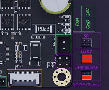
In standalone mode, it then looks like you need to jumper some of the pins on the VIO S header, but unfortunately documentation is lacking on how you should set them. VIO CGF0 and CFG1 control the microstepping. CGF2 and CGF3 are used for SPI/UART communication (they are SCK and CS on the drive connector header), but I don't know if they have any function in standalone mode. CFG4 is a complete mystery. CFG5 and CFG6 are used to set stealthChop/spreadCycle and motor current at standstill (either 100% or 50%). At least that's my reading of it.
There's a schematic in the BTT Github repository here that may help work out what needs to be jumpered: https://github.com/bigtreetech/BIGTREETECH-Stepper-Motor-Driver/blob/master/TMC5160T Plus/Hardware/BIGTREETECH TMC5160T Plus V1.0-SCH.pdf
See also:
https://bttwiki.com/TMC5160TPlus.html
https://cdn.shopify.com/s/files/1/1619/4791/files/BIGTREETECH_TMC5160T_Plus_User_Manual_96001abd-70ea-471d-a44b-b6df1913fa44.pdf
https://biqu.equipment/products/bigtreetech-tmc5160-v1-0-driver-spi-mode-silent-high-precision-stepstick-stepper-motor-driver-with-heatsink-for-skr-v1-3-gen-v1-4-reprapIan
Bed-slinger - Mini5+ WiFi/1LC | RRP Fisher v1 - D2 WiFi | Polargraph - D2 WiFi | TronXY X5S - 6HC/Roto | CNC router - 6HC | Tractus3D T1250 - D2 Eth
-
@droftarts thanks for taking the time to look at this. The remaining cfg pins are to set motor current. Its labeled on the back of the board but not in any documentation. I believe I have the other jumpers set correctly including Standalone mode. Tonight, I'll sketch up a simple schematic to show how the step stick adapter is labeled along with the voltages and a pic of the back. Probably too confusing to explain further without a visual representation.
-
@3DPMicro I notice you've connected 'en' enable. These drivers are usually enabled by default, and it's possible you're actually disabling it by connecting to 'en'. I recommend checking the TMC5160 documentation to see what signal the enable is expecting, along with what the other CFG pins do in standalone mode.
Yes, a picture of the back would be useful, assuming they've got it correct!
Ian