Print Cancelled and then printer Halted while printing
-
My printer has been running great, and then yesterday, the printer canceled the print, and then it went into emergency stop (it was printing for about 2hr. I tried simulating the GCODE and that was fine, so i printed the file and now after 15hr it stoped again. Since I'm running 3.5.3, I am going to update it to 3.5.4, although it doesn't appear that there is anything in the changelog about this. I am wondering why this would happen and how to fix it.
Since it halted after it did so the second time, i went over and looked at the console and then ran an M122 the console read this:
Canceled Printing file "file name here", print time was 15hr 36m
Emergency Stop! Reset the controller to continue
Info: status changed from Printing to HaltedAnd M122 red this
=== Diagnostics ===
RepRapFirmware for Duet 2 WiFi/Ethernet version 3.5.3 (2024-09-18 11:25:32) running on Duet WiFi 1.02 or later + DueX5v0.11
Board ID: 0JD2M-9F8TA-GJ4TJ-6J1FJ-3SJ6L-KNSL5
Used output buffers: 3 of 26 (26 max)
=== RTOS ===
Static ram: 23376
Dynamic ram: 75532 of which 12 recycled
Never used RAM 10672, free system stack 104 words
Tasks: NETWORK(2,nWait 6,16.6%,195) HEAT(3,suspended,0.1%,307) DUEX(5,nWait 5,0.0%,17) MAIN(1,running,80.5%,615) IDLE(0,ready,0.1%,29), total 97.2%
Owned mutexes:
=== Platform ===
Last reset 16:30:45 ago, cause: software
Last software reset at 2025-02-21 23:06, reason: User, Gcodes spinning, available RAM 7352, slot 2
Software reset code 0x0003 HFSR 0x00000000 CFSR 0x00000000 ICSR 0x0041f000 BFAR 0xe000ed38 SP 0x00000000 Task MAIN Freestk 0 n/a
Error status: 0x0c
Aux0 errors 0,0,0
MCU temperature: min 38.3, current 44.7, max 46.6
Supply voltage: min 23.5, current 24.0, max 24.7, under voltage events: 0, over voltage events: 0, power good: yes
Heap OK, handles allocated/used 99/14, heap memory allocated/used/recyclable 2048/356/136, gc cycles 0
Events: 0 queued, 0 completed
Driver 0: standstill, SG min 0
Driver 1: standstill, SG min 0
Driver 2: standstill, SG min n/a
Driver 3: standstill, SG min 0
Driver 4: standstill, SG min n/a
Driver 5: standstill, SG min 0
Driver 6: standstill, SG min 0
Driver 7: standstill, SG min 0
Driver 8: standstill, SG min 0
Driver 9: standstill, SG min 0
Driver 10:
Driver 11:
Date/time: 2025-02-22 15:37:14
Cache data hit count 4294967295
Slowest loop: 341.02ms; fastest: 0.14ms
I2C nak errors 0, send timeouts 0, receive timeouts 0, finishTimeouts 0, resets 0
=== Storage ===
Free file entries: 10
SD card 0 detected, interface speed: 20.0MBytes/sec
SD card longest read time 14.1ms, write time 30.8ms, max retries 0
=== Move ===
DMs created 83, segments created 43, maxWait 519354ms, bed compensation in use: mesh, height map offset 0.000, max steps late 0, min interval 0, bad calcs 0, ebfmin -0.00, ebfmax 1.00
no step interrupt scheduled
Moves shaped first try 0, on retry 0, too short 0, wrong shape 0, maybepossible 0
=== DDARing 0 ===
Scheduled moves 448761, completed 448746, hiccups 0, stepErrors 0, LaErrors 0, Underruns [7, 0, 0], CDDA state -1
=== Heat ===
Bed heaters -1 -1 -1 -1, chamber heaters -1 -1 -1 -1, ordering errs 0
=== GCodes ===
Movement locks held by null
HTTP is idle in state(s) 0
Telnet is idle in state(s) 0
File is idle in state(s) 0
USB is idle in state(s) 0
Aux is idle in state(s) 0
Trigger is idle in state(s) 0
Queue is idle in state(s) 0
LCD is idle in state(s) 0
Daemon is idle in state(s) 0
Autopause is idle in state(s) 0
Q0 segments left 0
Code queue 0 is empty
=== Filament sensors ===
check 334755368 clear 14601704
Extruder 0 sensor: ok
Extruder 1 sensor: ok
=== DueX ===
Read count 35, 0.04 reads/min
=== Network ===
Slowest loop: 220.57ms; fastest: 0.00ms
Responder states: HTTP(0) HTTP(0) HTTP(0) FTP(0) Telnet(0)
HTTP sessions: 1 of 8
=== WiFi ===
Interface state: active
Module is connected to access point
Failed messages: pending 0, notrdy 0, noresp 0
Firmware version 2.1.0
MAC address e8:68:e7:e1:4c:35
Module reset reason: Power up, Vcc 3.43, flash size 2097152, free heap 41372
WiFi IP address 192.168.0.237
Signal strength -30dBm, channel 6, mode 802.11n, reconnections 0
Clock register 00002002
Socket states: 0 0 0 0 0 0 0 0
Now, looking at the timing of it all. The software reset was 7min's before the printer halted; it says user; however, I didn't do anything and was not at the printer.
I would love any suggestion or help. I would love to know what happened so I can prevent this in the future.
-
Oh and heres the config.g
Modix BIG-180X, Duex Expansion, IDEX ; Configuration file for Duet WiFi (firmware version 3.4.5) ; Generated by Modix - Version 3.4.5 Config C global config_version = "Version 3.4.5 Config C" global generation = 4 ; generation 4 printer global printhead = 1 ; Griffin printhead global printheads = 2 ; dual extruder global expansion = 1 ; Duex expansion board is installed global idex = 1 ; idex setup ; for macro commands global pausetime = 0 ; record pauzing time global fan_0_speed = 0 ; Used to store the fan0 speed global fan_1_speed = 0 ; Used to store the fan1 speed global filamentswitch = 0 ; filament switch disabled (edited) global changer_count = 0 ; Counter for tool changer continous. global toolstate = 0 ; used for pauses ; General preferences_________________________________________________________ G90 ; send absolute coordinates... M83 ; ...but relative extruder moves M555 P2 ; Set output to look like Marlin M575 P1 B57600 S1 ; Set auxiliary serial port baud rate and require checksum (for PanelDue) ; Network_____________________________________________________________________ M550 P"Big-180X V4 - IDEX" ; set printer name ;M551 P"MODIX3D" ; Set password (optional) M98 P"config_networking.g" ; enable network G4 P300 ; wait 300ms ;M552 P0.0.0.0 ; Uncomment this command for using Duet Ethernet board ; Drives_________________________________________________________________________ ;Main board______________________________________________________________________ M569 P0 S1 ; Physical drive 0. X-B-M M569 P1 S0 ; Physical drive 1. X-F-M M569 P2 S0 ; Physical drive 2. U Secondary M569 P3 S1 ; Physical drive 3. E0-Extruder. M569 P4 S0 ; Physical drive 4. E1-Extruder. ;Duex5 board_____________________________________________________________________ M569 P5 S0 ; Physical drive 5. Y M569 P6 S1 ; Physical drive 6. Z-Back-Left (ZBL) M569 P7 S1 ; Physical drive 7. Z-Front-Left (ZFL) M569 P8 S1 ; Physical drive 8. Z-Front-Right (ZFR) M569 P9 S1 ; Physical drive 9. Z-Back-Right (ZBR) ;Settings_________________________________________________________ M584 X0:1 Y5 U2 Z6:7:8:9 E3:4 P4 ; Driver mapping M671 X-185:-185:668:668 Y668:-46:-46:668 S30 ; Anticlockwise ;___________________________________________________________________ M350 X16 Y16 Z16 U16 E16:16 I1 ; Configure microstepping with interpolation M92 X80 Y80 U80 Z2000 E425.09 ; Set steps per mm M566 X500 Y500 U500 Z30 E3000:3000 P1 ; Set maximum instantaneous speed changes (mm/min) M203 X18000 Y18000 U18000 Z400 E6000:6000 ; Set maximum speeds (mm/min) M201 X3000 Y3000 U3000 Z240 E1000:1000 ; Set accelerations (mm/s^2) M204 P1000 T3000 ; Set print and travel accelerations (mm/s^2) M906 X1800 Y1800 U1800 Z1800 E1000:1000 I50 ; Set motor currents (mA) and motor idle factor in per cent M84 S100 ; Set idle timeout - 100 seconds ; Axis Limits M208 X0 Y0 U0 Z-2 S1 ; set axis minima M208 X1800 Y600 Z600 S0 ; set axis maxima M98 P"config_probe_offset_U.g" ; Endstops M574 X1 S1 P"duex.e5stop + duex.e6stop" ; configure switch-type (e.g. microswitch) endstop for low end on X via pin e5stop + e6stop M574 Y1 S1 P"duex.e4stop" ; configure switch-type (e.g. microswitch) endstop for low end on Y via pin e4stop M574 U2 S1 P"duex.e3stop" ; configure switch-type (e.g. microswitch) endstop for low end on Secondary via pin e3stop ; Automatic Z Offset Calibration____________________________________ M574 Z1 S1 P"!duex.e2stop" ; configure switch-type for Automatic z-offset ; Z-Probe M558 P9 C"zprobe.in" H4 F180 T12000 A1 R0.5 ; BLTouch probing settings M950 S0 C"duex.pwm5" ; sets the BLTouch probe M376 H100 ; Height (mm) over which to taper off the bed compensation G31 P500 X0 Y32.4 ; BLTouch X and Y offset M557 X{move.axes[0].min + sensors.probes[0].offsets[0] + 1, move.axes[0].max + sensors.probes[0].offsets[0] - 1} Y{move.axes[1].min + sensors.probes[0].offsets[1] + 1, move.axes[1].max + sensors.probes[0].offsets[1] - 1} P30:10 ; The M557 is used to define the mesh grid area. It uses the P parameter to set the amount of probing points. P10:10 would be a 10x10 grid. Supports up to a 21x21 grid. M98 P"config_probe.g" ; Load the Z-offset from the config_probe.g file ; The Z_offset value is now set in config_probe.g, not in config.g ; Adjust the values there, do not adjust anything here. ; Heaters___________________________________________________________ M140 H-1 ; disable heated bed (overrides default heater mapping) ;E0_________________________________________________________________ ;M308 S0 P"e0temp" Y"thermistor" T100000 B4725 ; configure sensor 0 as thermistor on pin e0temp ;M308 S0 P"spi.cs1" Y"rtd-max31865" ; Configure sensor 0 as PT100 via the daughterboard M308 S0 P"e0temp" Y"pt1000" ; Configure sensor 0 as PT1000 on pin e0temp M950 H0 C"e0heat" T0 ; create nozzle heater output on e0heat and map it to sensor 0 M98 P"PID_tune_E0.g" R1 ; PID calibration M143 H0 S300 ; set temperature limit for heater 0 to 285C ;E1_________________________________________________________________ ;M308 S1 P"e1temp" Y"thermistor" T100000 B4725 ; configure sensor 1 as thermistor on pin e1temp ;M308 S1 P"spi.cs2" Y"rtd-max31865" ; Configure sensor 1 as PT100 via the daughterboard M308 S1 P"e1temp" Y"pt1000" ; Configure sensor 1 as PT1000 on pin e1temp M950 H1 C"e1heat" T1 ; create nozzle heater output on e1heat and map it to sensor 1 M98 P"PID_tune_E1.g" R1 ; PID calibration M143 H1 S300 ; set temperature limit for heater 1 to 285C ; Fans______________________________________________________________ M950 F0 C"fan0" Q500 ; create fan 0 on pin fan0 and set its frequency M106 P0 S0 H-1 C"Primary blower fan" ; set fan 0 value. Thermostatic control is turned on M950 F1 C"fan1" Q500 ; create fan 1 on pin fan1 and set its frequency M106 P1 S0 H-1 C"Secondary blower fan" ; set fan 1 value. Thermostatic control is turned on M950 F3 C"duex.fan5" Q500 ; create fan 3 on pin fan5 and set its frequency M106 P3 S255 H0 T45 ; set fan 3 value. Thermostatic control is turned on M950 F4 C"duex.fan6" Q500 ; create fan 4 on pin fan6 and set its frequency M106 P4 S255 H1 T45 ; set fan 4 value. Thermostatic control is turned on ; LED______________________________________________________________ M950 F2 C"duex.fan7" Q500 ; create LED on pin fan7 and set its frequency M106 P2 S0 H-1 C"LED Primary" ; Disable fan channel for LED M950 F5 C"duex.fan8" Q500 ; create LED ENC on pin fan8 and set its frequency M106 P5 S0 H-1 C"LED ENC" ; Disable fan channel for LED M950 F6 C"duex.fan4" Q500 ; create LED Secondary on pin fan4 and set its frequency M106 P6 S0 H-1 C"LED Secondary" ; Disable fan channel for LED M106 P5 S255 ; Enclosure LED on by default M106 P2 S255 ; Secondary LED on by default M106 P6 S255 ; Primary LED on by default ; Tools______________________________________________________________ ;T0_________________________________________________________________ M563 P0 S"E0 Primary" D0 H0 F0 ; define tool 0 G10 P0 X0 Y0 Z0 ; set tool 0 axis offsets G10 P0 S210 R180 ; set initial tool 0 active and standby temperatures to 210 and 180c by default ;T1_________________________________________________________________ M563 P1 S"E1 Secondary" D1 H1 F1 Y3 ; define tool 1 G10 P1 X0 Y0 Z-3 ; set tool 1 axis offsets M98 P"config_probe_secondary.g" ; Set secondary Z-Offset M98 P"config_probe_offset_X.g" ; Set secondary Z-Offset G10 P1 S210 R180 ; set initial tool 1 active and standby temperatures to 210 and 180c by default ; Automatic power saving____________________________________________ M911 S22.0 R23.5 P"M913 X0 Y0 U0 G91 M83 G1 Z3 E-5 F1000" ; Set voltage thresholds and actions to run on power loss. Power Failure Pause ; Primary hotend Clog detector__________________________________________________ M591 D0 P7 C"e0stop" S1 L3.14 E10 R10:300 ; Clog Detector E0 [Add-On] ;Secondary hotend Clog detector__________________________________________________ M591 D1 P7 C"e1stop" S1 L3.14 E10 R10:300 ; Clog Detector E1 [Add-On] ; Crash detector__________________________________________________ M950 J2 C"zstop" ; create Input Pin 2 on pin E4 to for M581 Command. ;M581 P2 T0 S0 R0 ; Crash Detector [Add-On] ; Emergency stop button__________________________________________________ M950 J3 C"ystop" ; create Input Pin 3 on pin ystop to for M581 Command. M950 J4 C"xstop" ; create Input Pin 4 on pin xstop to for M581 Command. M581 P3 T0 S1 R0 ; Emergency stop [Add-On] ;M581 P4 T0 S1 R0 ; Emergency stop [Add-On] -
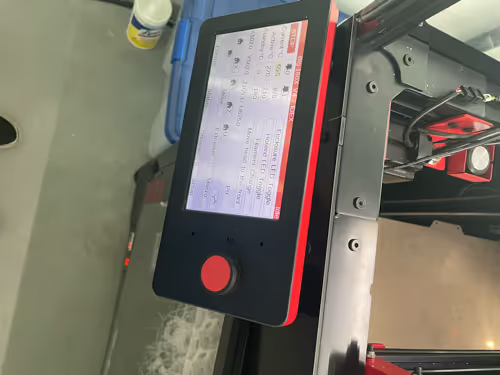
@mballin it appears that the machine received an Emergency Stop command. If you have a PanelDue attached, the Emergency Stop button could have been triggered either by something touching it or by the enclosure you put it in pressing too hard against the corner of the screen. There s also an Emergency Stop button in DWC, if you had a DWC session attached.
We've also occasionally seen bogus commands executed when the cable to the PanelDue picks up noise; so make sure that the PaneDue cable is kept well away from other cables, especially stepper motor cables.
Duet WiFi hardware designer and firmware engineer
Please do not ask me for Duet support via PM or email, use the forum
http://www.escher3d.com, https://miscsolutions.wordpress.com -
@dc42 Thank you, that is helpful. I did some rerouting of USB cables for cameras; other than that, I haven't changed any of the cable locations, but I will look at the cable to the PanelDue to see if it's near anything else and change that. Ill also try and revert all USB cables that i changed just to eliminate that problem
Is there a way to see where the emergency stop command was sent from, I would be curious to know where it is happening to narrow down the problem.
I was not connected to the DWC or actually physically at the printer when this happened. I am going to try and recreate the problem tomorrow/ run a print and see what happens. I will also check the emergency stop cable and ensure it operates correctly.
I assume this doesn't have anything to do with the gcode, but i am going to regenerate it with settings of successful prints from the past.
I will update this post with what I find. My only other guess would be that someone else hit the emergency stop button, which would be quite annoying; maybe I have to go look at the security footage.
Thank you!
-
@mballin Looking at the Modix Facebook, it could also be a faulty emergency stop button, tbd if that is the issue
-
@mballin is there a physical button wired to the duet for e-stop?
-
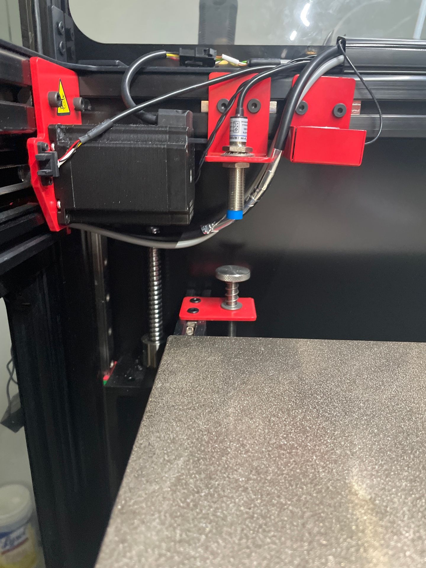
@T3P3Tony, yes, there is. My finger is on the LCD screen cable, which is quite close to this stepper motor. I unplugged the emergency stop button and tried to reroute the cable. Unfortunately, there is not a lot of length to route the cable better.
I resliced another print, disconnected the emergency stop button (per Modix Facebook page of someone having a similar issue), tried to move the cable a bit farther away from that stepper motor (see last photo), and also updated to 3.5.4. Lets hope that solves it. I am wondering if there is a way to get more detailed logging of where the emergency stop comes from, but lets hope these fixes solve it.
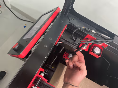
Moved Cable
-
@mballin Ended up being the emergency stop switch, after removing was able to print with no problem! Thanks for the help!
-
 undefined Phaedrux marked this topic as a question
-
undefined Phaedrux has marked this topic as solved