'DuePrint' with a Duet 3 6HC - Stratasys Dimension Conversion
-
First of all, major thanks to @AJ-Quick, @drphil3d, @Archeantus and @Pete_A for their previous posts regarding converting the Stratasys Dimension, Fortus (250), and uPrint models over to the Duet ecosystem, as I doubt I would have been able to get as far as I have without their previous research, experimentation, and engineering. A great thread here, resulting in this awesome Hackaday post detailing @Archeantus 's fully reversible conversion.
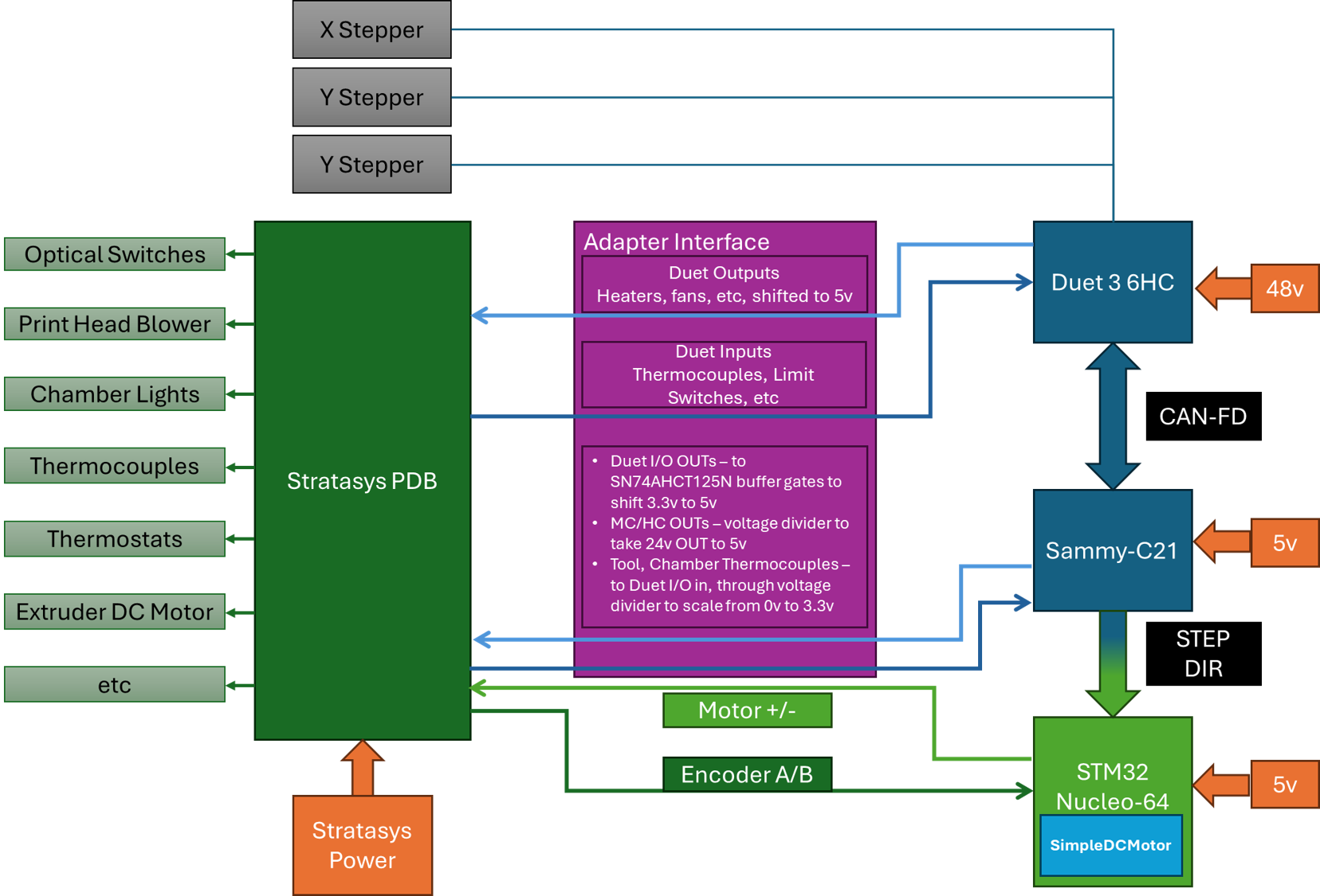
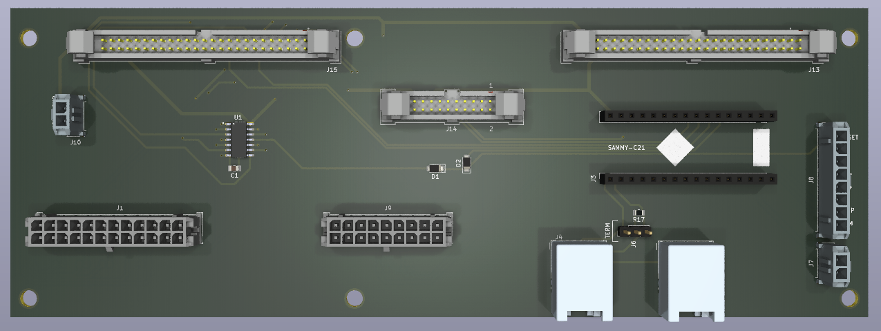
My twist on this was to instead of using the Duet 2 product line, attempt the conversion with a Duet 3 6HC and Sammy-C21. Block diagram updated April 2025
The fully reversible approach is quite great because it's likely the easiest way to convert one of these machines, as the existing motion, sensing, and extruding hardware is solid. Other approaches, in my opinion, are implemented by swapping in substandard hardware, and at greater time & expense.
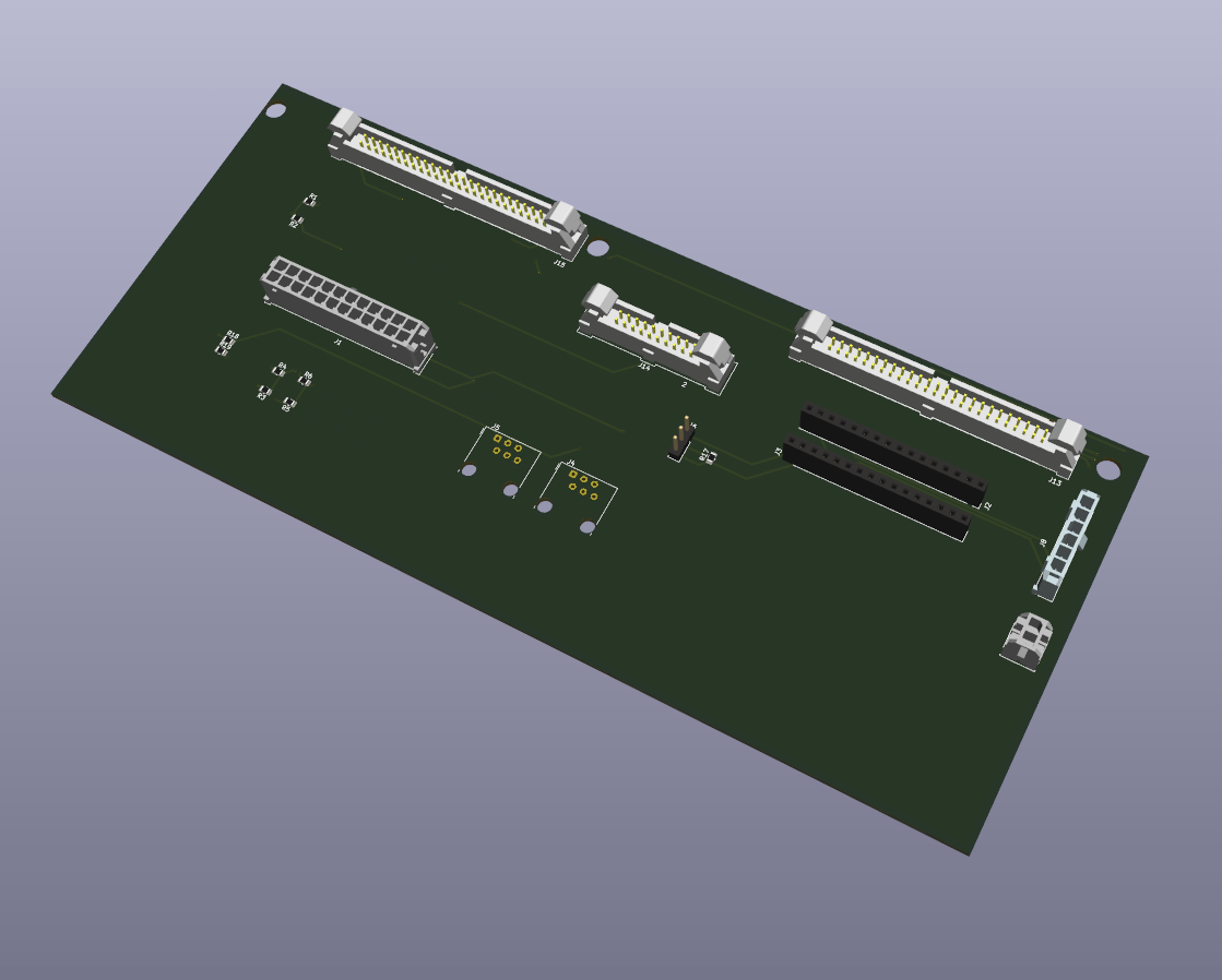
Ultimate goal is to have an adapter board that would simplify the conversion process (notional setup below); now that the motors and the bulk of the inputs/outputs can be managed, I think I can move on to refining the board.
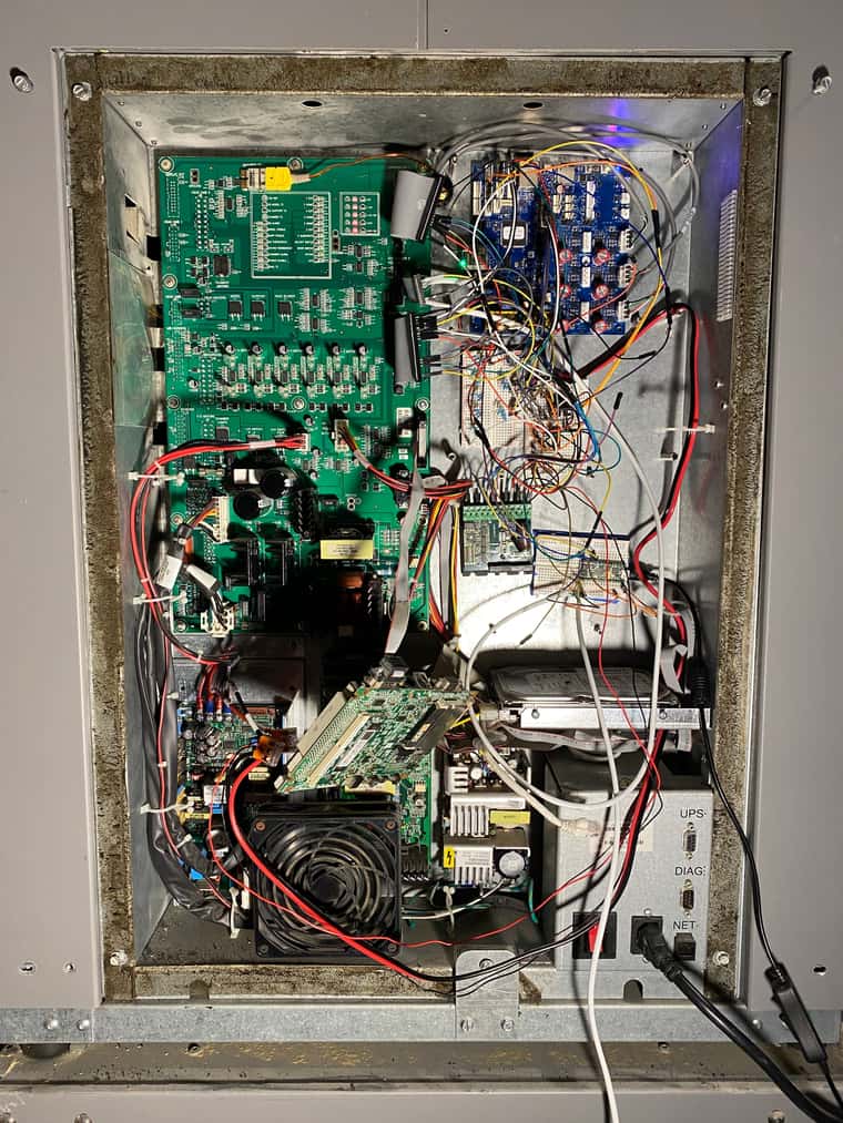
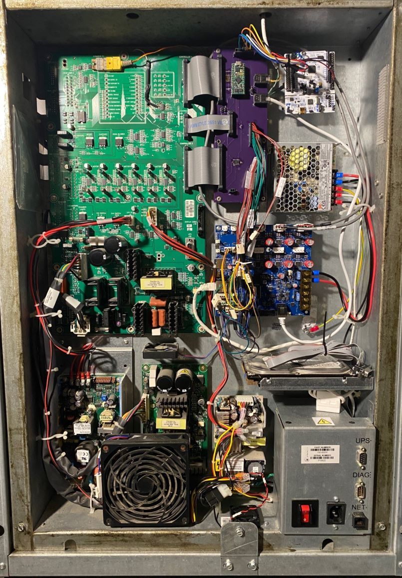
For now though, the electronics enclosure is very much a living, breathing organism

What is the current status?
Able to move the motors, home the axes, power on the heaters, and print!What are the next major next steps?
Tool change, probe, nozzle cleaning macros need to be fully fleshed out. Would like to integrate the 9x limit/position switches into the configuration as best I can (X, Y, Z home, X, Y, Z end of travel, Z probe, Model toggle, Support Toggle)What won't I be tackling in this project:
- Will not attempt to integrate the existing front user interface/screen. Instead, I'll likely pull that module out, and install a PI and touchscreen (do not intend to run the Duet with the SBC attached however)
What I haven't yet tested:
- Anything with the material bay. The user who posted the Hackaday project did some initial integration efforts, once I'm confident with the bulk of the printing portion of the printer, I'll look into the material bay control (less to use the material spools, but more to help loading in filament).
- Have not tested thermostat outputs as inputs on the Duet, but that should be low effort.
Something that surprised you?
I had previously experimented with driving the Geckodrive G320X with a Duet 2/ Duex, but I was genuinely surprised I was immediately able to get it moving as required with the Sammy-C21 STEP/DIR pins- was expecting to have to do a lot more fiddling!April 2025 Update - I don't recommend the G320x. A much better solution is documented below.
Motor Control:
- Bypass the Stratasys PDB for the X, Y, and Z motors, instead wire directly to them from the 6HC
- Use the Sammy-C21 (default firmware build) to interface with a
Geckodrive G320xSTM32 Nucleo-64 via STEP/DIR. TheGeckodriveNucleo-64 interfaces with the PDB to control the DC motor for the extruder(the G320x actually doesn't directly connect to the motor armatures, rather it goes through to a L298P full bridge driver. In this application, the G320X is mainly used just to gain closed loop control of the motor). - Instead of a Sammy-C21, a Duet 1XD could most likely be used.
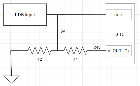
Temperature Sensing:
There are three temperature sensors to interface with, all three are K-Type thermocouples. While the chamber thermocouple terminates inside the electronics enclosure, the two hotend thermocouples are terminated and processed in the print head. From the PDB the processed analog voltage spans from 0v (low temp) to 5v (high temp). To be read by the Duet temperature inputs, the analog voltages go through voltage dividers to get down to scale from 0v to 3.3v.I validated the temperature range by soldering a few wires onto the existing Stratasys Control board, and running a print (with the original control board, SBC, etc), logging the values via a Labjack T7 DAQ. At the same time, I fed the analog voltages to the Duet, finding that ~1v was applies to the sensor inputs, biasing the temperature high. Once I made that discovery it was pretty straightforward to correct my M308 B and C values.
Limit Switches (Optical Switches):
I fed the limit switch outputs directly from the PDB to the 6HC inputs (5v signal, 6HC's inputs are 30v tolerant).Enabling Head Blower Fan, LED Lights, etc:
A few ways of doing this - ultimately you need to send 5v to the PDB. To use the I/O headers, I used SN74AHCT125N level shifters to take 3v to 5v.To use the low current outputs, this works well:
Plenty more to work on, but for now, proof of life:
https://www.youtube.com/watch?v=rRLwZSXlzxI -
I love to see it! I would definitely pick up a plug and play version to convert one of my machines if you end up making them. I was hoping for something that keeps more of the Strata electronics in place, but figuring out how to interface directly was what killed my attempt. Driving the motors directly and the servo through a Gecko makes it far easier.
-
@AJ-Quick Once again, my sincerest thanks for your previous work!
Once the interface board is in a useable state, I would be happy to send you one!
To your point on the motors, that is the only part of the Duet that’s likely used to its potential, as for the most part we’re just using RRF and the board to control I/O, as the PDB does all the heavy lifting for things like heaters and whatnot. The 6x stepper drivers on the Duet are overkill (we only use three of them, and off the top of my head the motors are rated at 2A, 2.8A, and 2.8A for X, Y, and Z), and we’re running the board off half its rated voltage. The Geckodrive is also overrated for the application, it could be used for much larger motors, but instead we’re using it simply for control signals.
A custom board (or possibly even an appropriate evaluation kit) could possibly be enough to support all the needed I/O channels. Of course then you’d have to solve the motor control issue, though perhaps that results in using a Duet 3HC via CAN-FD.
Not a problem I’m prepared to solve, happy enough to use the 6HC!
-
Getting closer with the adapter board:
One Item I've just started to look into, but haven't yet worked out is enabling the PDB without the SBC attached. @AJ-Quick unsure if you ran into any issues disconnecting the SBC power cable (4-pin Molex 8981 connector) - initially on power up all power LED status lights are on, and the 5V/12V power supply is outputting voltage. After a few seconds, the 5V/12V power supply cycles between on and off. I wonder if the 5V/12V power supply has some sort of minimum load?
I believe I've got the correct set of pins on the PDB getting power, simply having only the power connector connected to the SBC (no hard drive I/O or power, no display) allows it to power on correctly.
Video of issue: https://www.youtube.com/watch?v=GKUwO8F4w1w
Edit: Power supply in question is P/N LPT62, reading the datasheet, minimum loads are .7A on the 5V line, and .3A on the 12V line.
-
 undefined sebkritikel referenced this topic
-
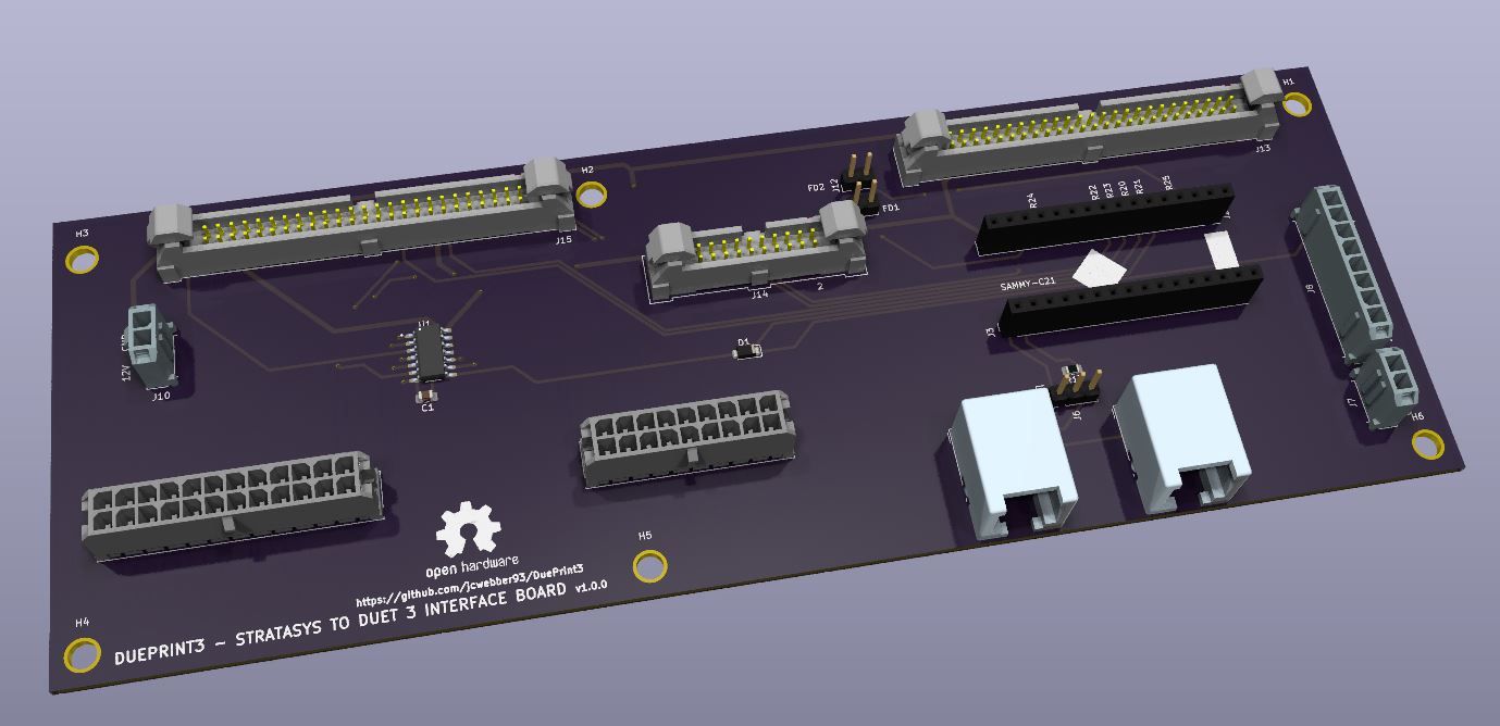
Time for an update! Files published here: https://github.com/jcwebber93/DuePrint3/
Includes- Interface Board KiCad Project
- Detailed BOM
- Wire List (from-to)
- RRF configuration files
Major changes:
- Received, built, and tested the v1.1.0 interface board. I recognize its not that complicated of a design... but it works! Chief issue - functions that are driven by the OUT_X headers are powered on once power is applied to the system. This is bad in that, once power is applied, but before the 6HC fully initializes, the chamber and extruder heaters blip on. If the system is powered on, with the Duet not yet loaded with an updated config.g, the heaters will turn on. I need to address this, pretty major oversight.
- Added a small 48V power supply to power the 6HC (and by extension the stepper motors). Gives a bit of extra speed.
- Swapped out the Geckodrive G320x for a STM32 Nucleo-64 running SimpleDCMotor (derived from SimpleFOC). Several weeks back, I lost extrusion control. Extruder motor control is PWM signals (Stratasys control board, G320x, Nucleo-64, etc) -> series resistor -> 74AC14 hex inverter w/Schmitt Trigger -> L298 -> DC motor. I found I had burnt up a series resistor, as well as the 74AC14! On the Dimension 1200 PDB, the series resistors are 121ohm, while on the uPrint PDBs, they are 1k ohm. Based on some additional bench testing, I believe the G320x in this application outputs a peak voltage (and/or current?) that is much too high for the 74AC14s used on this PDB, as isn't intended to be used as logic control. I repaired the board (one damaged pad later...), but still needed a method of consuming STEP/DIR and outputting a signal to drive the extruder motor. Came across the SimpleDCMotor extension of SimpleFOC, which was quite straightforward to implement.
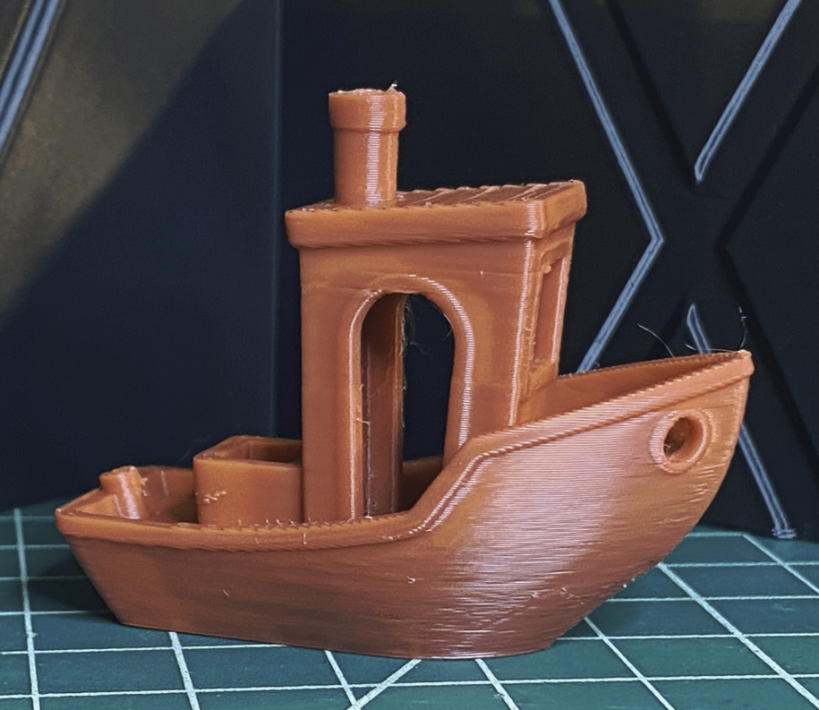
Not too bad for an ABS Benchy printed at ~200mm/s at 305°c hotend, 75°C chamber! Plenty more tuning to do.