diagonal line on print causing layer shifting?
-
@53581
Bang-bang control on the bed could cause kind of stripes.
As far as i can see, your config. may have been created for an older firmware. The heater parameters have changed with 3.4.
I don't know if that really makes a difference.
But I would change to PWM-control and autotune the bed heater and the tool.
Please also post the content of config-override.g as the parameters should be stored there.....(UTC+1)
-
@DIY-O-Sphere I did not even realize I had bang bang on the bed! That would fit with the idea that the layer time effects it. I printed that gear in vase mode, and it was very good. I also tried a Prusa slicer, no change.
-
@DIY-O-Sphere - Can you post the gcode file for the gear?
-
This post is deleted! -
I opened the gcode file in PrusaSlicer and I don't see anything that looks like it would cause those shifts. The layer thickness is .3mm and each layer in the gcode is following the same path, with a variation in the 3rd decimal. This means I don't think there is anything coming in from the slicer X and Y positions or extrusion rate.
One thing I wonder about (because I'm not a spiral vase user) is whether there might be any effect on printing due to the very small Z moves with each new segment extruded. Can your Z stepper resolve the typical .001mm move on each segment? What's the smallest Z step your printer can do? I assume that if a z move is smaller than the printer resolution, RRF will accumulate the Z moves unti a full step (or micro-step) is used to "catch up". But I don't think this is the cause because if it was, then I'd expect to see the sane defect in the same place on every layer.
Which brings me back to the possibility of the bed shifting slightly during printing. I'd look at the defects on opposite X and Y sides to see if the defect shows matching shifts.
And unrelated to the print defects, I think you might want to look at the tooth generator, assuming this is an involute gear profile. The gcode path looks like an involute at the outboard part of the tooth, but has a little kink about half-way to the root of the tooth. It should be a nice rolling path (an involute) .
-
The Ender 3 runs on v-rollers. You might have a flat spot on a roller or some dirt collection on the rails?
If it was real level shifting, you'd also see it on the inside, but it looks OK there. -
"What's the smallest Z step your printer can do?" To be honest I am not sure! they are just stock ender 3 stepper Moters. If it is something mechanical, I am not sure how it is consistent enough to travel up the side of the part like that.
-
@Phaedrux
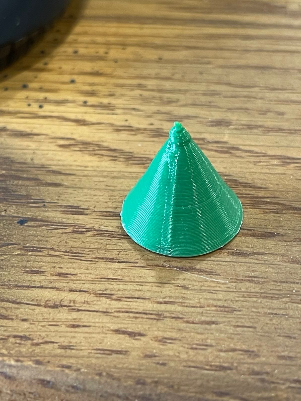
I think these like pretty good. -
I was thinking something a lot larger/taller than that so you can start to see any repeating patterns.
Try a taller cylinder and conical cylinder in vase mode.
-
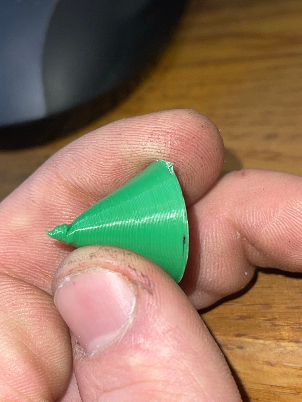
After more testing I Think I am getting z binding on both sides. This would explain why the artifacts do not travel straight through the part but rather make separate patterns on the wall closest to their respective sides while leaving the center looking ok.
-
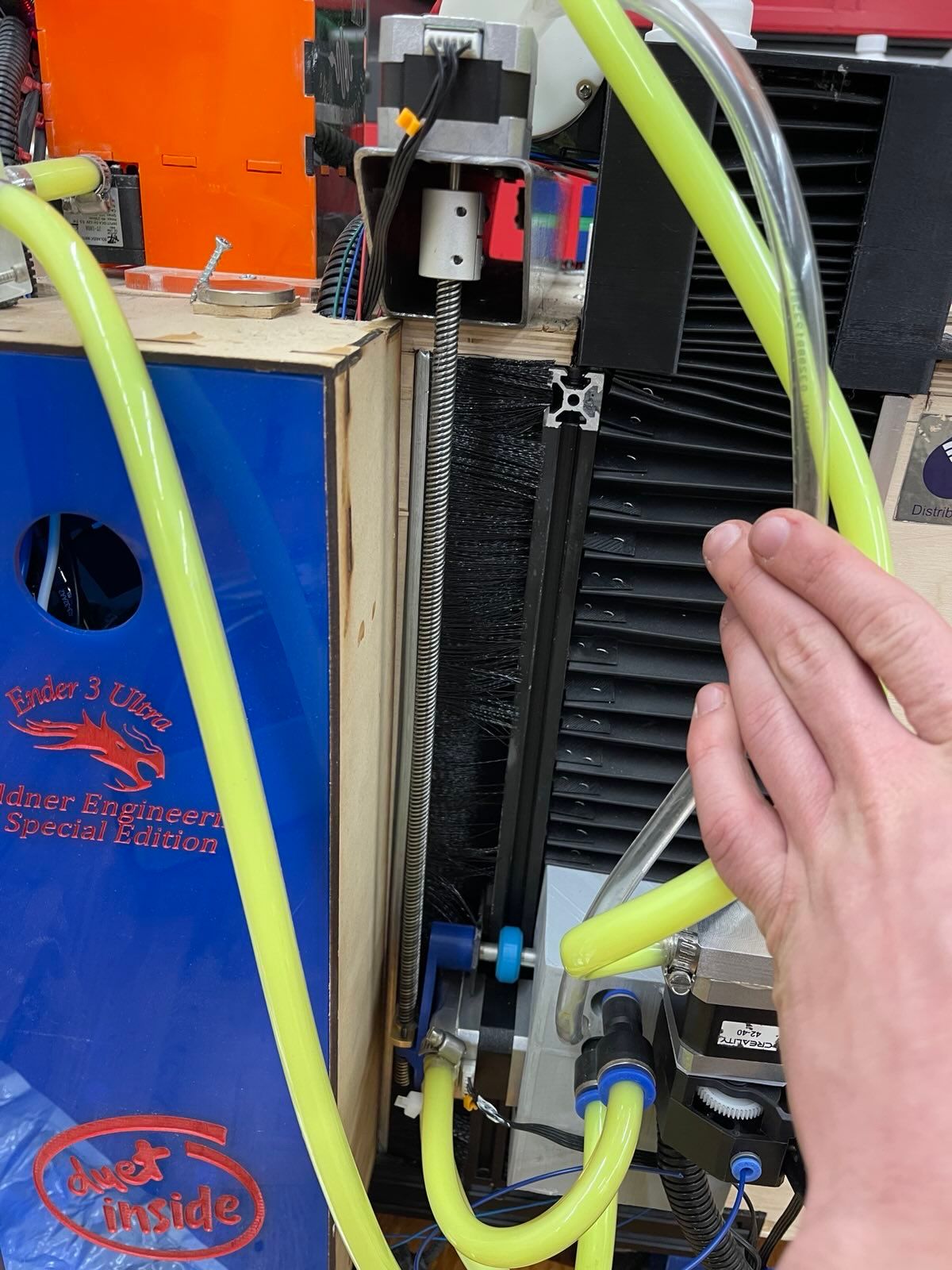
So the way I have my z steppers hooked up the whole x axes hangs on it rather than pushing on it, does this make a difference?
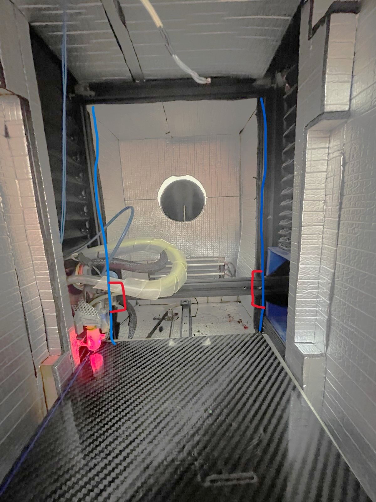 this is how I plan to fix it I will a add linear bearings for the blue lines and then somehow mount the linear bearing cars to the x in a way that it can pivot so it can move independently.
 -
@53581 said in diagonal line on print causing layer shifting?:
a add linear bearings for the blue lines and then somehow mount the linear bearing cars to the x in a way that it can pivot so it can move independently.
To avoid axis' binding, you need to fix one side while the other side can "float" in one direction to compensate thermal expansion.