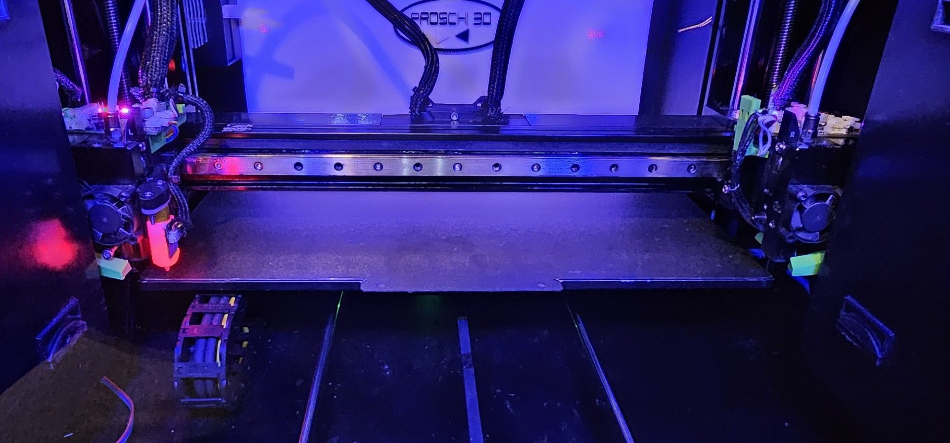
Neopixel not working after install komponents
-
@Phaedrux Yes, it worked flawlessly before. However, I did the update to 3.5.2 on all components at the same time right after the hardware installation.
For example, when I send M150 E1 B255 S16, the command goes through without error, but the neopixel remains off. I have also connected a second neopixel for testing, but without success.
-
What firmware were you on before 3.5.2 rc1? Can you try going back?
-
@Phaedrux Yes, I will go back to 3.5.0 tomorrow to test it. I will report back then.
-
I just tried it with the firmware that was installed before, unfortunately without success, the LED does not turn on.
-
I'm not super fluent with neo pixels. How do you have it connected?
-
@Phaedrux
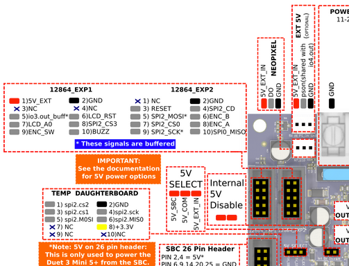
I connected them to the Neopixel output on the Duet Mini, and it worked until I connected the other hardware. I connected the first Duet to the tool distribution board, then the two tool boards, and on the tool distribution board’s CAN out, a second Duet Mini. They also don’t work on the second Duet, I’ve already tried that.M950 E1 C"led" T1 U16 -
And if you remove the newly added hardware?
Do you have any seperate way of confirming that Neopixel is still functional at all? -
@Phaedrux I’ve ordered some new ones again that I will test. But actually, I can’t imagine that all of them have broken down together. We will see.
-
@Phaedrux
I have now connected a new neopixel, without success. I cannot explain why it no longer works. Neither on one duet mini nor on the other.Perhaps someone here who operates the neopixel on the duet3 mini with firmware 5.1.2 rc1 can post the config.g and the M150 commands?
-
@Proschi78 How is the LED strip wired? Does it connect to 5V and GND on the NEOPIXEL connector? Or have you connected to different 5V and GND pins?
The 5V_EXT_IN pin on the NEOPIXEL connector needs to be supplied by an external 5V source. See the Mini 5+ tab here https://docs.duet3d.com/User_manual/Connecting_hardware/IO_Neopixel_DotStar#connections
You can wire the LED 5V and GND to the 5V_EXT and GND on the 12864_EXP1 connector to test. But RGB LEDs typically use up to 60mA per LED, you have 16, so up to 720mA. If the LEDs were powered from the internal 5V, it may be that, with the addition of the other components, it is drawing too much current from the 5V regulator which has a limit of 1A total. The 5V regulator also has to run the rest of the low voltage circuitry, eg MCU, screens, power for CAN bus communication etc.
I've just tested this on RRF 3.5.1, and LEDs work correctly on the 'led' output, with 5V and GND wired to the 12864_EXP1 connector. I used these commands:
M950 E1 C"led" T1 U16
M150 E1 B255 S16
I only had 7 RGB LEDs connected, but they all lit up blue. If you connect yours like this, try just lighting up the first LED, with
M150 E1 B255 S1
Ian
-
@droftarts Thanks first of all. I will try it this way, with an external power supply.
-
@droftarts it works
 !
!
-
 undefined Phaedrux marked this topic as a question
-
 undefined Phaedrux has marked this topic as solved