VFD PWM Signal Control from Duet 2 Problems
-
Working on a new project to have the Duet 2 board control very large motors. I have little to no experience with VFDs (variable frequency drives). I am trying to have the PWM signal from the expansion pins run the drive, but I am unable to understand/figure out why it does not work. I think it has something to do with the frequency, frequency type, or voltage, but can not figure it out.
Perhaps it has to do with M569 in the duet config?
M569 P9 S1 R0 T4
Duet config is attached. config.gI was able to have the VFD be controlled by a cheap PWM signal generator, but not from the Duet board, as shown in this video: https://youtu.be/IXPVMlhlvyg
Attached is a portion of the VFD manual that pertains to pulse signal input. 305-313.pdf
A full manual can be found here, but is a large file pdf:
https://cdn.automationdirect.com/static/manuals/gs20m/gs20m.html
https://cdn.automationdirect.com/static/manuals/gs20m/gs20m.pdfSettings from Default we have changed on the VFD:
00.04- 22
9.10- 50
10.00- 5
10.01- 200
10.16- 5
10.31- 80
10.32- 6
10.34- 2.77
10.38- 16.67
10.52- 15
Full List of current drive settings: https://docs.google.com/spreadsheets/d/1prs4KkhvBQm4M302XxjzF-e8wH6MWPT-/edit?usp=sharing&ouid=105160618684698464112&rtpof=true&sd=trueI am aware of PWM to analog signal conversion devices, such as this https://www.amazon.com/gp/product/B08CRKRBX4/ref=ppx_yo_dt_b_search_asin_title?ie=UTF8&psc=1 We were able to get this working, but we do not want to use this type of device that can cause inaccuracies.
Willing to even put a cash bounty on this starting at $10. Can pay over paypal.
-
 undefined Phaedrux marked this topic as a question
-
@3DPotter how have you connected the VFD to the Duet? I don't see a M950 command in your config.g to set up a PWM output port.
-
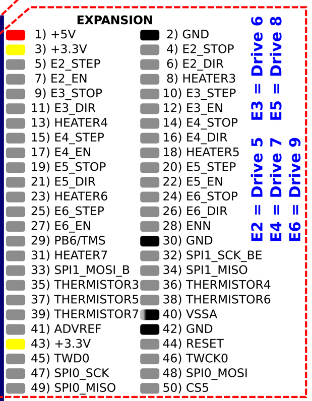
@dc42 We are connecting it via the expansion slot pins. M569 P9 S1 R0 T4. The E6 pin: Pin 25 and Pin 2
There may have been a word/grammar miscommunication. When I said PWM above, I was referring to the STEP signal.
We are not using any fan or heater connectors on the board currently.
Perhaps it is the amplitude of the pulses that needs to be greater? Is there a way to do this? I may be wildly not correct for doing this, but the voltage output using a multi-meter always measures 0.6v from Pin 25 to 2 when an extruder move command is sent. ~0v during idle. On the cheap pulse generator device, the output is always 6.5v when in use. (I do not have an oscilloscope).

(PS: sorry for the 1 month delay, other project got in the way).
-
 undefined 3DPotter has marked this topic as solved