1HCL Tuning Issues
-
Hey Everyone,
I had annoying issues with my boards after i got them and gave up for a while. I now have some time to play around with them again and thought I might try and get some help. I have been trying to tune my system. It is a CoreXY with the 1HCL boards on the X and Y axis. They are 0.9 degree LDO motors with 2500CPR encoders. I have the system homing and also calibrating ok, however, when trying to do the PID tuning I keep running into issues.
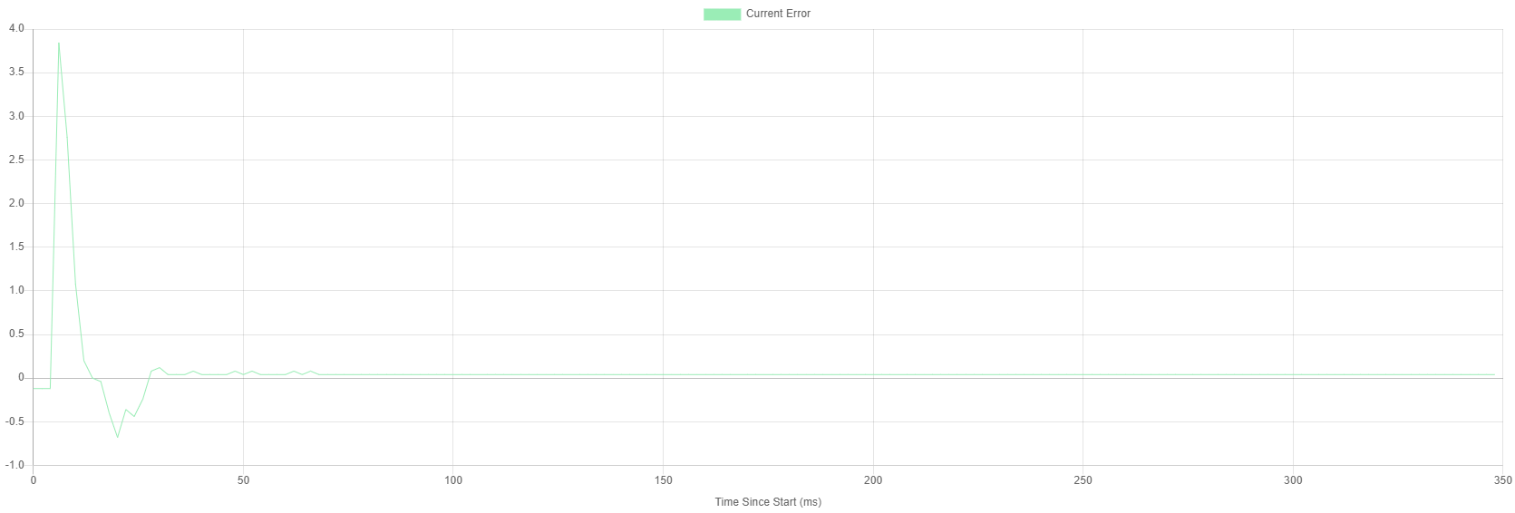
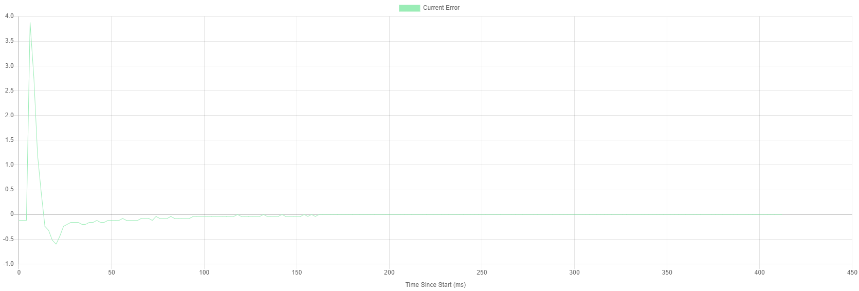
My error on the beginning of the move is close to 4 steps and no matter what I change, it does not fix the issue.
See config below and graph below that (All on version 3.4.3)
; Configuration file for Duet 3 (firmware version 3.3)
; executed by the firmware on start-up
;
; generated by RepRapFirmware Configuration Tool v3.3.10 on Wed Dec 08 2021 21:12:19 GMT+1300 (New Zealand Daylight Time)

; General preferences
M575 P1 S1 B57600                                               		; enable support for PanelDue
G90                                                             		; send absolute coordinates...
M83                                                             		; ...but relative extruder moves
M550 P"Sam's Printer"                                           		; set printer name
M669 K1                                                         		; select CoreXY mode

; Wait a moment for the CAN expansion boards to start
G4 S2

; Network
M552 P0.0.0.0 S1                                                		; enable network and acquire dynamic address via DHCP
M586 P0 S1                                                      		; enable HTTP
M586 P1 S0                                                      		; disable FTP
M586 P2 S0                                                      		; disable Telnet

; Drives

M569 P10.0 D4 S0 F8														; Configure the motor on the 1HCL at can address 50 as being in closed-loop drive mode (D4) and not reversed (S0)
M569 P11.0 D4 S0 F8														; Configure the motor on the 1HCL at can address 51 as being in closed-loop drive mode (D4) and not reversed (S0)
M569.1 P10.0 T2 C6.25 R100 I0 D0                                         ; Configure the 1HCL board at CAN address 10 with a quadrature encoder on the motor shaft that has 20 steps per motor full step
M569.1 P11.0 T2 C6.25 R100 I0 D0                                         ; Configure the 1HCL board at CAN address 11 with a quadrature encoder on the motor shaft that has 20 steps per motor full step
M569 P0.2 S0 F10                                                 		; physical drive 0.2 goes forwards
M569 P0.3 S0 F10                                                   		; physical drive 0.3 goes forwards
M569 P0.4 S1 F10                                                   		; physical drive 0.4 goes forwards
M569 P0.5 S1 F10                                                   		; physical drive 0.5 goes forwards
M569 P20.0 S1                                                  			; physical drive 20.0 goes forwards
M584 X10.0 Y11.0 Z0.2:0.3:0.4:0.5 E20.0 P6                    			; set drive mapping
M350 X32 Y32 															; configure microstepping
M350 Z16:16:16:16 U16 V16 W16 E16 I1                       				; configure microstepping with interpolation
M92 X320 Y320 Z400:400:400:400 U400 V400 W400 E690	       				; set steps per mm
M566 X800 Y800 Z120:120:120:120 U120 V120 W120 E300  	       			; set maximum instantaneous speed changes (mm/min)
M203 X60000 Y60000 Z400:400:400:400 U400 V400 W400 E7200       			; set maximum speeds (mm/min)
M201 X30000 Y30000 Z250:250:250:250 U250 V250 W250 E10000          		; set accelerations (mm/s^2)
M906 X1550 Y1550 Z1800:1800:1800:1800 U1800 V1800 W1800 E1200 I60   	; set motor currents (mA) and motor idle factor in per cent
M84 S30                                                        			; Set idle timeout
M917 X75 Y75 																; Set the closed loop axes to have a holding current of zero

; Axis Limits
M208 X0 Y0 Z0 S1                                               			; set axis minima
M208 X363.5 Y352 Z412:412:412:412 U412 V412 W412 S0                     ; set axis maxima
M671 X-45:-46:408:405 Y92:296:300:92 S3.0  								; Define the X and Y coordinates of the lead screw. Motor order: FL (1), RL (2), RR (3), FR (4).Snn Maximum correction in mm to apply to each leadscrew

; Endstops
M574 X1 S1 P"10.io0.in"                                       	 		; configure switch-type (e.g. microswitch) endstop for low end on X via pin 11.io0.in
M574 Y1 S1 P"10.io1.in"                                        			; configure switch-type (e.g. microswitch) endstop for low end on Y via pin 11.io2.in
M574 Z1 S2                                                      		; configure Z-probe endstop for low end on Z

; Z-Probe
M558 P8 R1.0 C"!^20.io2.in" H5 F250		                            	; set Z probe type to unmodulated and the dive height + speeds
G31 P500 X0 Y0 Z-0.20                                          		; set Z probe trigger value, offset and trigger height
M557 X0:363.5 Y10:352 S20                                     			; define mesh grid

; Heaters
M308 S0 P"spi.cs0" Y"rtd-max31865"                              		; configure sensor 0 as PT100 on pin spi.cs1
M950 H0 C"out1" T0                                              		; create bed heater output on out0 and map it to sensor 0
M307 H0 R0.200 K0.148:0.000 D38.10 E1.35 S1.00 B0                       ; disable bang-bang mode for the nozzle heater and set PWM limit
M140 H0                                                         		; map heated bed to heater 0
M143 H0 S150                                                    		; set temperature limit for heater 0 to 150C
M308 S1 P"20.temp0" Y"pt1000"                                  			; configure sensor 1 as PT1000 on pin 123.temp0
M950 H1 C"20.out0" T1                                          			; create nozzle heater output on 123.out0 and map it to sensor 1
M307 H1 R2.366 K0.162:0.000 D9.88 E1.35 S1.00 B0 V24.0					; PID control Magnum Plus PT1000
;M307 H1 R2.104 C430.2 D9.13 S1.00 V24.2									; PID control Magnum Plus PT1000
M143 H1 S400                                                    		; set temperature limit for heater 1 to 400C

; Fans

; Part Cooling Pump

M950 F3 c"out2" Q25000													; Assign Part Cooling Fan to Heater Port 2
M106 P3 X0.5 B0 H-1 C"Part Cooling" 									; Part Cooling Fan Remap to Heater 2

; Water Cooling

M950 F4 c"!out6+out6.tach"												; Water Cooling Pump Output
M106 P4 H1 B15 L0.2 X.75 T50 C"Extruder"								; Water Cooling Pump Start
M308 S10 P"temp0" Y"thermistor" A"Water Temp" T10000 B3950				; Create Heater for Cooling Water
M950 F0 c"!out9" Q25000													; Assign Fan 0 to Fan 0 Port and Inverse
M106 P0 H10 L.3 B.5 T60:80 C"Radiator"									; Set fan 4 PWR fan. Turns on when Radiator temperature (heater 103), hits 30C and full speed when the temperature reaches 60C

;Board Cooling Fan

M308 S20 P"mcutemp" Y"mcutemp" A"Duet Board" 							; Map Duet MCU to the Extra Table
M308 S21 P"10.mcutemp" Y"10.mcutemp" A"Board 10 MCU"					; Map Duet Drivers to the Extra Table
M308 S22 P"11.mcutemp" Y"11.mcutemp" A"Board 11 MCU"					; Map Duex2 Driver to the Extra Tabl
M308 S23 P"20.mcutemp" Y"20.mcutemp" A"Tool Board MCU"					; Map Duex2 Driver to the Extra Tabl
M308 S24 P"temp1" Y"thermistor" A"Control Area" T100000 B3950  			; Create Virtual Heater for Control Area
M950 F1 c"!out4+out4.tach" Q25000										; Assign Fan 1 to Fan 1 Port and Inverse
M106 P1 L.3 B.5 T40:65 H20 C"Duet Fan"									; Set fan 1 PWR fan. Turns on when MCU temperature, hits 45C and full when the MCU temperature reaches 65C or if any TMC2660 drivers (virtual
M950 F2 c"!out5+out5.tach" Q25000										; Assign Fan 2 to Fan 2 Port and Inverse
M106 P2 L.3 B.5 T40:65 H22 C"Control Area"								; Set fan 2 PWR fan. Turns on when MCU temperature, hits 45C and full when the MCU temperature reaches 65C or if any TMC2660 drivers (virtual

; Tools
M563 P0 S"Extruder 1" D0 H1 F3 											; define tool 0
G10 P0 X0 Y0 Z0                                                			; set tool 0 axis offsets
G10 P0 R0 S0                                                   			; set initial tool 0 active and standby temperatures to 0C
M955 P20.0 I24															; Accelerometer
M572 D0 S0.005															; Pressure Advance
;M592 D0 A0.009541 B0.001755											; Non Linear Extrusion 0.4mm pla
M593 P"zvddd" F60														; Input Shaping


;Filament out sensor

M591 D0 P3 C"20.io1.in" S0 R70:130 L26.26 E3.0 							; magnet sensor for extruder 0 is connected to E2 endstop input, enabled, sensitivity 24.8mm.rev, 70% to 130% tolerance, 3mm detection length 25.88
M591 D0 																; display filament sensor parameters for extruder drive 0

;Tool Board Buttons
M950 J10 C"20.button1"
M581 T2 P10 S1

; Custom settings are not defined

; Miscellaneous
M911 S20 R23 P"M913 X0 Y0 G91 M83 G1 Z3 E-5 F1000"             			; set voltage thresholds and actions to run on power loss
This is my error with my settings at P110 I0 and D0

And this is it with P110 I5000 D0.15

Can anyone shed any light on why my error could be so high initially. I am doing 1000 samples at 500 samples per second. My currents are all 100. This is only the X axis as well. I have been making parameter changes to both the X and Y at the same time.
Cheers
Sam -
@samlogan87 an initial error of 4 full steps is completely normal when performing tuning using the step move. This is because the step move commands an instant movement of 4 full steps, and of course the motor can't change position instantaneously.
-
@dc42 silly me. I can’t believe I didn’t think about that. That makes sense now. Does that tuning look ok to you?
The other thing, I have 0.9 steppers. I see in some documentation that you now don’t recommend them. Is there a reason why. I got mine from LDO last year and Jason said that they were the ones that he was working with you guys on.
Cheers
Sam -
@samlogan87 your tuning doesn't look bad, however you do have a little overshoot. You might want to increase the D parameter to reduce the overshoot.
We do have 0.9deg steppers from LDO in one of our machines. The reasons we no longer recommend using 0.9deg motors with the EXP1HCL are:
-
The maximum step rate achievable by the EXP1HCL is limited by the speed of the firmware PID loop and also by how fast the driver can change the current in the motor windings. The same step rate on a 0.9deg motor gives you half the speed of a similar 1.8deg motor.
-
0.9deg motors need higher resolution encoders than 1.8deg motors, because the EXP1HCL needs to measure position to within a fraction of a full step.
-
The effects of backlash in the encoder and motor friction are more severe when using 0.9deg motors, because a given amount of backlash is a larger fraction of a full step.
-
-
@dc42 thanks for your reply. I will try bump it up a bit. It does sometime become unstable however if I increase D. Will play around more. How many oscillations should you be aiming for about setpoint? I have done a bit with PID in pump stations and heating, but nothing with response like this/required accuracy.
Ok cool. Thanks for explaining. I might talk to Jason and see if he can send me the motors without encoders and will swap them over as he said at some stage he would get 1.8 degree motors sorted.
Cheers
Sam