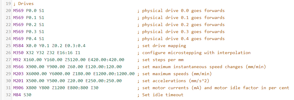
Help how do i configure two drivers for the Z axis
-
How to configure two drivers for the Z axis?
I have one motor connected to driver 2. And the other to driver 3
-
@gasstaldy said in Help how do i configure two drivers for the Z axis:
I have one motor connected to driver 2. And the other to driver 3
Your M584 would need to change. Currently driver 3 is an extruder, so you'd need to move it to the Z axis.
M584 X0.0 Y0.1 Z0.2:0.3 E0.4If you have 2 extruders, you'd need another driver for it as well. Otherwise you can remove the double values for the extruder from the other commands you show. Like
M92 E420.00:420.00would only beM92 E420. Also note that the Z axis (or any other none extruder axis) doesn't need multiple values. Only extruders. A single value will apply to all drivers in a motion axis. -
@phaedrux thank you, I see that it is quite simple, I just couldn't find where to start
-
You can see an example here: https://docs.duet3d.com/en/User_manual/Connecting_hardware/Z_probe_auto_levelling
-
@phaedrux Thanks, the Z axes turned out well.
Now I have the problem that the extruder does not appear in DWG or in the Duet panel; Drives M569 P0.0 S1 ; physical drive 0.0 goes forwards //X M569 P0.1 S1 ; physical drive 0.1 goes forwards //Y M569 P0.2 S1 ; physical drive 0.2 goes forwards //Z M569 P0.3 S0 ; physical drive 0.3 goes forwards //Z M569 P0.4 S1 ; physical drive 0.4 goes forwards //E M584 X0.0 Y0.1 Z0.2:0.3 E0.4 ; set drive mapping M350 X32 Y32 Z16 E16 I1 ; configure microstepping with interpolation M92 X160.21 Y160.28 Z400.00 E420.00 ; set steps per mm M566 X900.00 Y900.00 Z60.00 E120.00 ; set maximum instantaneous speed changes (mm/min) //cambios instantaneos de direccion (jerk) M203 X21000.00 Y21000.00 Z500 E3000.00 ; set maximum speeds (mm/min) //Maximas velocidades que puede alvanzar los ejes M201 X6000 Y6000 Z20 E250.00 ; set accelerations (mm/s^2) //la forma en la que acelera por segundo los ejes M906 X800 Y800 Z1100 E800 I30 ; set motor currents (mA) and motor idle factor in per cent M84 S30 ; Set idle timeout ; Axis Limits M208 X0 Y0 Z0 S1 ; set axis minima M208 X600 Y570 Z498.75 S0 ; set axis maxima ; Endstops M574 X1 S1 P"!io1.in" ; configure switch-type (e.g. microswitch) endstop for low end on X via pin !io1.in M574 Y1 S1 P"!^io2.in" ; configure switch-type (e.g. microswitch) endstop for low end on Y via pin !^io2.in M574 Z2 S1 P"!^io3.in" ; configure switch-type (e.g. microswitch) endstop for high end on Z via pin !^io3.in ; Z-Probe M950 S0 C"io4.out" ; create servo pin 0 for BLTouch M558 P9 C"io4.in" H5 F6000 T6000 P5 ; set Z probe type to bltouch and the dive height + speeds //H altura a la que se despliega la sonda G31 P500 X45 Y0 Z-0.71 ; set Z probe trigger value, offset and trigger height //-3.04 M557 X0:600 Y0:570 S150 ; define mesh grid ; Heaters M308 S0 P"temp0" Y"thermistor" T100000 B3950 ;U"TMK8" ; configure sensor 0 as thermistor on pin temp0 //U nombre del sensor M950 H0 C"out1" T0 ; create nozzle heater output on out1 and map it to sensor 0 //H numero de hotend - M307 H0 B0 S1.00 ; disable bang-bang mode for heater and set PWM limit M143 H0 S280 ; set temperature limit for heater 0 to 280C ; Fans M950 F0 C"out8" Q500 ; create fan 0 on pin out8 and set its frequency M106 P0 C"FanExtrusor" S0 H0 T100 ; set fan 0 name and value. Thermostatic control is turned on M950 F1 C"out7" Q500 ; create fan 1 on pin out7 and set its frequency M106 P1 C"FanCapa" S1 H-1 ; set fan 1 name and value. Thermostatic control is turned off ; Tools M563 P1 S"MK8" D1 H0 F0:1 ; define tool 1 G10 P1 X0 Y0 Z0 ; set tool 1 axis offsets G10 P1 R0 S0 ; set initial tool 1 active and standby temperatures to 0C ; Custom settings are not defined ; Miscellaneous M501 ; load saved parameters from non-volatile memory M911 S10 R11 P"M913 X0 Y0 G91 M83 G1 Z3 E-5 F1000" ; set voltage thresholds and actions to run on power loss T1 ; select first tool -
@gasstaldy I believe you need to define Tool 0 and not Tool 1. You probably need to change your config similar to the one listed below.
; Tools M563 P0 S"MK8" D0 H0 F0:1 ; define tool 0 G10 P0 X0 Y0 Z0 ; set tool 0 axis offsets G10 P0 R0 S0 ; set initial tool 0 active and standby temperatures to 0C T0 ; select first tool -
@gasstaldy don’t assign thermostatically controlled fans to tools. Your fan 0 is assigned as such, so remove it from the M563 tool definition.
Ian