Formbot 400
-
; Configuration file for Duet WiFi (firmware version 1.20 or newer)
; executed by the firmware on start-up; --- general preferences ---
M111 S0 ; debugging off
G21 ; work in millimetres
G90 ; send absolute coordinates
M83 ; relative extruder moves
M555 P2 ; set firmware compatibility to look like MarlinM667 S1 ; select CoreXY mode
M208 X-5 Y-15 Z0 S1 ; set axis min to end of safe travel.
M208 X408 Y403 Z510 S0 ; set axis max to match endstop location.; ---filament sensing---
M591 D0 P1 C"e0_stop" S0; Automatic power saving
M911 S21 R23 P"M913 X0 Y0 G91 M83 G1 Z0 E-3 F1000" ; Set voltage thresholds and actions to run on power loss; --- endstops ---
M574 X2 S1 P"^xstop"
M574 Y2 S1 P"^ystop"; Z-Probe
; Original 2.20 bltouch
;M574 Z1 S0 ; Set endstops controlled by probe
;M307 H7 A-1 C-1 D-1 ; Disable heater on PWM channel for BLTouch
;M558 P5 X0 Y0 Z1 H5 F300 T6000 ; Set Z probe type to bltouch and the dive height + speeds; New 3.0 bltouch
;M574 Z0 P"nil" ; no Z endstop switch, free up Z endstop input
M558 P9 C"^zprobe.in" H6 R1 F400 T15000 A1 S0.03 ;BLTouch connected to Z probe IN pin
M950 S0 C"duex.pwm5";M574 Z1 S1 ; Set endstops controlled by probe
G31 P25 X0 Y21 Z0.35 ;.6 ,1.45 .4 ,1.35 ; Set Z probe trigger value, offset and trigger height
M557 X20:380 Y20:380 S50 ; Define mesh grid
M376 H10; --- drives ---
M569 P0 S1 D2 B2 Y4:4 F4; X
M569 P1 S1 D2 B2 Y4:4 F4; Y
;M569 P2 S0 D2 ; Z
;M569 P3 S1 D2 B0 Y7:7 F2; E0
M569 P3 S1 D2 B1 Y7:5 F3; E0
;M569 P4 S1 D2 ; E1
; -- duex --
M569 P5 S1 D2 B1 Y7:4 F4 ; Z5
M569 P6 S0 D2 B1 Y7:4 F4 ; Z6
M569 P7 S1 D2 B1 Y7:4 F4 ; Z7
M569 P8 S0 D2 B1 Y7:4 F4 ; Z8M569 P2 R-1
M569 P4 R-1
M569 P9 R-1;M915 X Y S10 R2 H400 F1
;M915 Z S7 R2 H200 F1
; --- z-axis stepper leveling configuration ---
M584 X0 Y1 E3 Z6:5:8:7 ; four motors, at 5, 6, 7, and 8
M671 X-65:-65:465:465 Y475:-15:-15:475 S20 ; Z belts at 4 corners; --- drive map ---
; _______
; | 6 | 7 |
; | ----- |
; | 5 | 8 |
; -------
; frontM350 X16 Y16 E16 Z16 I1 ; microstepping with interpolation (I1)
M92 X80 Y80 Z400 E685 ; steps per mm - with bt
M566 X900 Y900 Z120 E600 P1 ; maximum instantaneous speed changes (mm/min) (jerk)
M203 X24000 Y24000 Z2400 E4200 ; maximum speeds (mm/min)
M201 X5000 Y5000 Z300 E3000 ; max accelerations
M204 P4000 T4000 ; print accelerations
M906 X1200 Y1200 Z1200 E700 I40 ; motor currents (mA) and motor idle factor in per cent
M917 X70 Y70 Z80 E70
M593 F35
M84 S3600 ; set idle timeout; Network
M550 P"ROB" ; Set machine name
M552 S1 ; Enable network
M586 P0 S1 ; Enable HTTP
M586 P1 S0 ; Disable FTP
M586 P2 S0 ; Disable Telnet
; --- firmware retraction ---
;M207 S2.5 R0 F6000 T4500 Z0 ; [ Snnn positive length to retract, in mm ]
; [ Rnnn positive or negative additional length to un-retract, in mm ]
; [ Fnnn retraction feedrate, in mm/min ]
; [ Tnnn feedrate for un-retraction if different from retraction, mm/min ]
; [ Znnn additional zlift/hop ]; --- heaters ---
M308 S0 P"bed_temp" Y"thermistor" T100000 B4138 C0 R4700 ; define bed temperature sensor
M308 S1 P"e0_temp" Y"thermistor" T100000 B4138 C0 R4700 ; define E0 temperature sensor
M950 H0 C"bed_heat" T0 ; heater 0 uses the bed_heat pin, sensor 0
M950 H1 C"e0_heat" T1 ; heater 1 uses the e0_heat pin and sensor 1
M140H0;M305 P0 T100000 B4138 C0 R4700 ; set thermistor + ADC parameters for heater 0
M307 H0 A-1 C-1 D-1 ; set PID tuned settings for heater 0
M143 H0 S140 ; set temperature limit for heater 0 to 120C
;M305 P1 T100000 B4138 C0 R4700 ; set thermistor + ADC parameters for heater 1
M307 H1 A517.3 C213.3 D11.1 V24.3 B0 ; set PID tuned settings for heater 1
M143 H1 S380 ; set temperature limit for heater 1 to 280C; --- tools ---
M563 P0 D0 H1 ; define tool 0
G10 P0 X0 Y0 Z0 ; set tool 0 axis offsets
G10 P0 R0 S0 ; set initial tool 0 active and standby temperatures to 0C; --- fans ---
M950 F0 C"fan0" ; Fan 0 uses the Fan0 output
M950 F1 C"fan1" ; Fan 1 uses the Fan1 output
M950 F2 C"fan2" ; Fan 2 uses the Fan2 output
M106 P0 S0 I0 F500 H-1 ; Set fan 0 value, PWM signal inversion and frequency. Thermostatic control is turned off
M106 P1 S0.95 I0 F500 H1 T50 ; Set fan 1 value, PWM signal inversion and frequency. Thermostatic control is turned on
M106 P2 S.55 I0 F500 H1 T50 ; Set fan 2 value, PWM signal inversion and frequency. Thermostatic control is turned onM572 D0 S.04
;M572 D0 S.4 ; Linear Advance
;M592 D0 A0.01 B0.0005 ;nonlinear extrusion; --- RGB leds - White ---
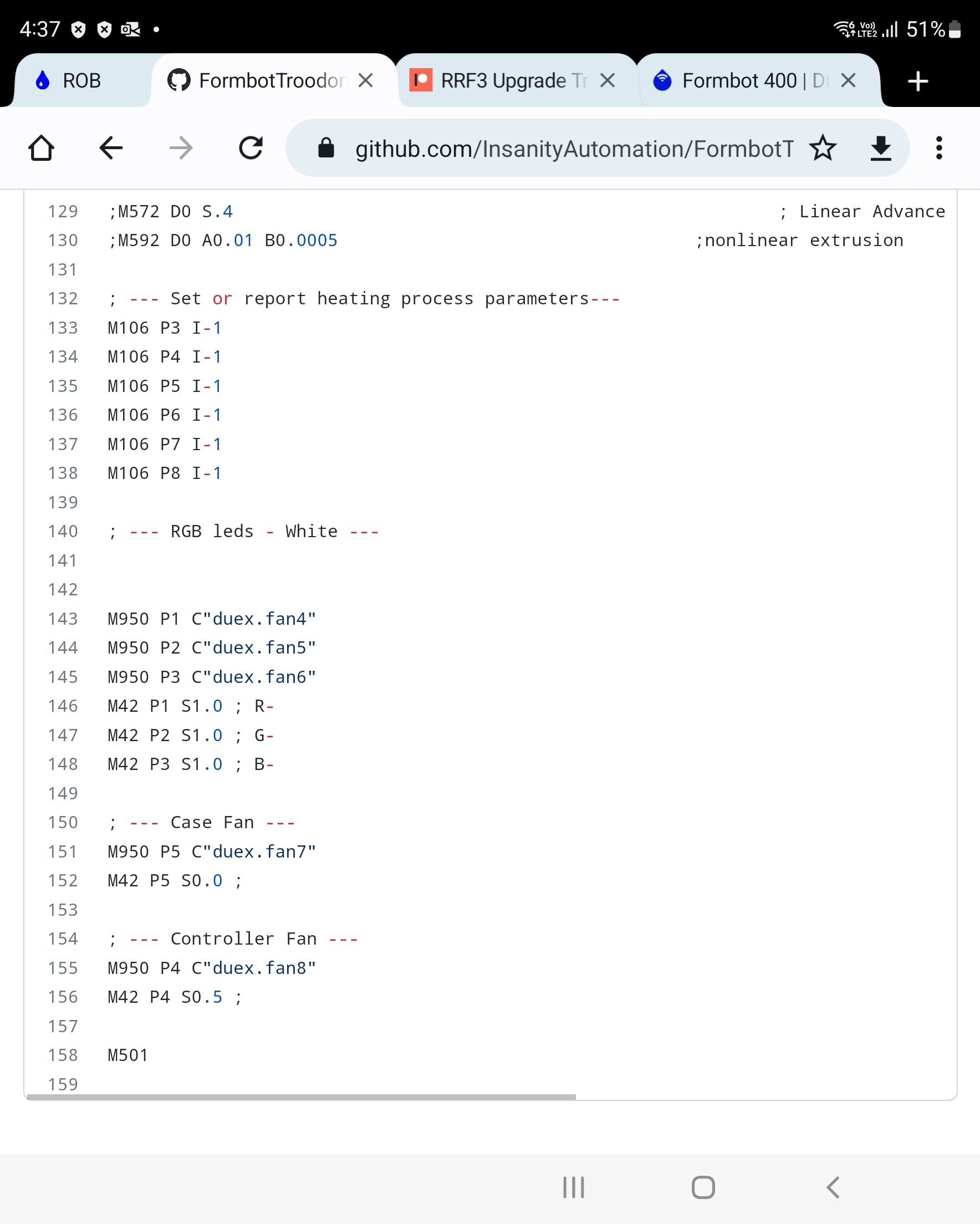
M950 P1 C"duex.fan4"
M950 P2 C"duex.fan5"
M950 P3 C"duex.fan6"
M42 P1 S1.0 ; R-
M42 P2 S1.0 ; G-
M42 P3 S1.0 ; B-; --- Case Fan ---
M950 P5 C"duex.fan7"
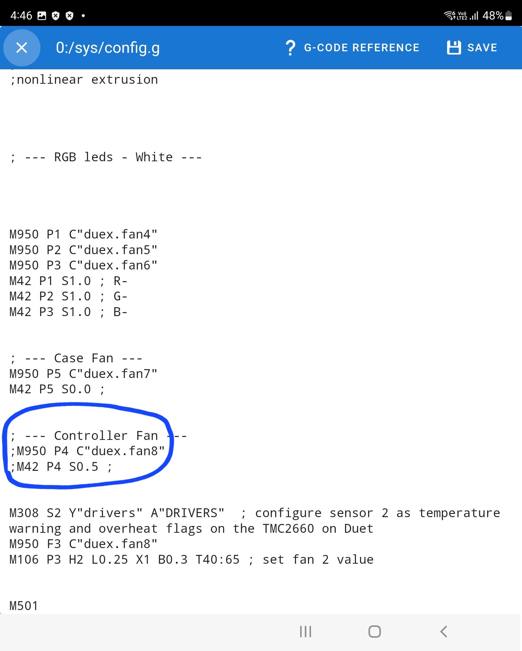
M42 P5 S0.0 ;; --- Controller Fan ---
;M950 P4 C"duex.fan8"
;M42 P4 S0.5 ;M308 S2 Y"drivers" A"DRIVERS" ; configure sensor 2 as temperature warning and overheat flags on the TMC2660 on Duet
M950 F3 C"duex.fan8"
M106 P3 H2 L0.25 X1 B0.3 T40:65 ; set fan 2 valueM501
-
You need a corresponding M950 command to create the pin that the M42 command then controls.
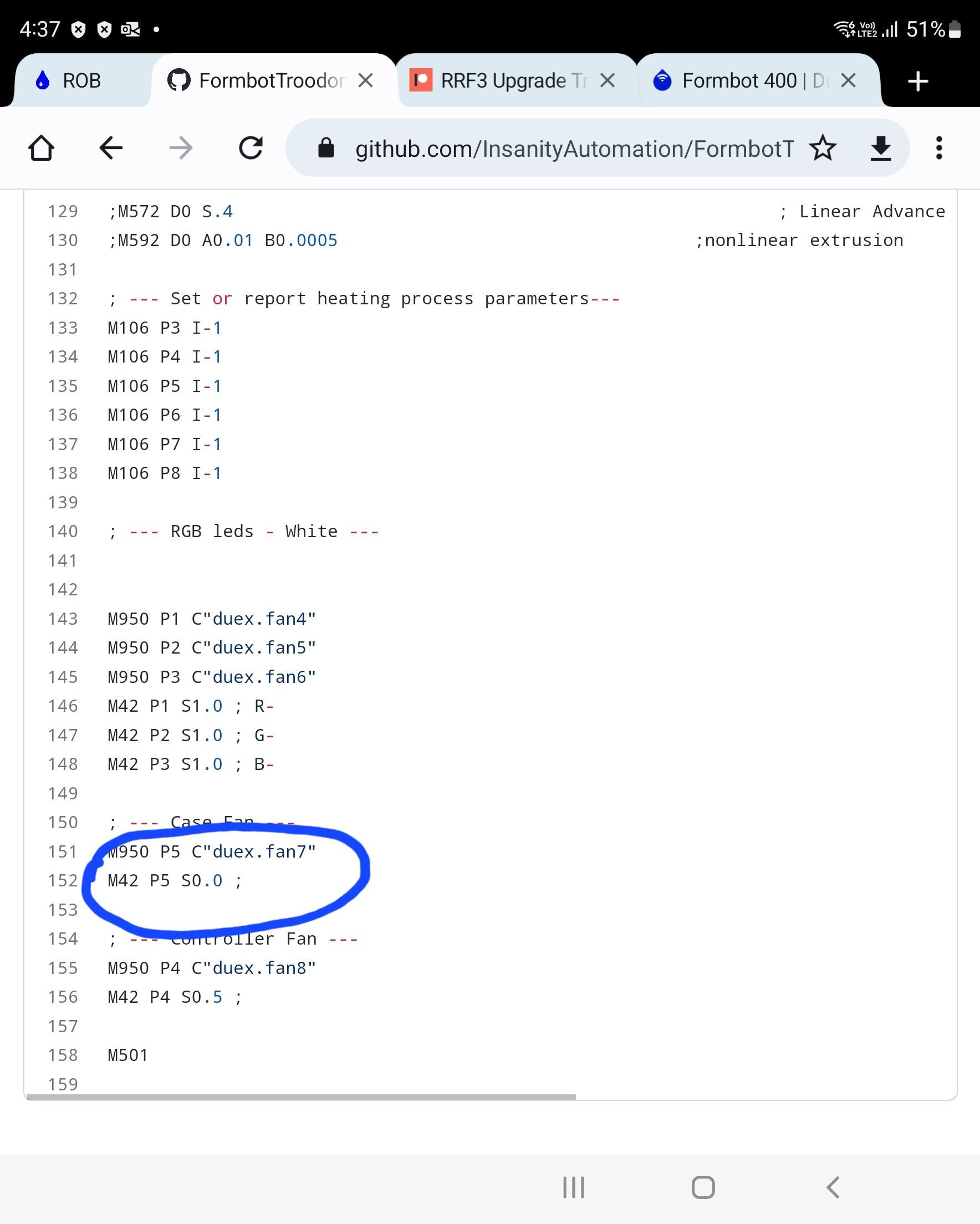
An example of such a combinations from your config is the fans
; --- Case Fan ---
M950 P5 C"duex.fan7"
M42 P5 S0.0 ;
What is your air filtration macro actually controlling?
-
@phaedrux said in Formbot 400:
command
It's controlling a huge fan at the back of the printer to filter air with different spin percentages from 20% to 50% to 80 to 100.
-
Seems weird to use a fan with M42 instead of M106. I'm not sure what the reason to do that would be.
At any rate, you'd still need an M950 command that creates the pin for M42 to use.
What port is the fan actually connected to on the board?
-
@phaedrux well I don't know but I have the settings that worked with reprap 2.0 below it shows what pin it is connected to but how can I configure this in my macro settings just copy and past from 2.0 to 3.0
;; Convenience macro to make this script be a button on the UI,
;; for cases when the built-in filament load/unload UI won't work.
;; NOTE you still need to have the tool selected before running this macro
;; or you'll get errors.M42 P5 S1.0
-
@unknowx said in Formbot 400:
well I don't know
You don't know where it's physically plugged into the board?
-
@phaedrux well no because I didn't open to see the board but the old macro config that worked fine states p5 so it must be port 5
-
Is it this one?
; --- Case Fan ---
M950 P5 C"duex.fan7"
M42 P5 S0.0 ;If that's where it's physically connected then your air filter macro needs to change to 5.
Either way, we need a pin name, like this C"duex.fan7"
-
@phaedrux well below is the config for reprap 2.0 which was working fine and the fan name and pin is the same but for reprap 3.0 it's not working see below

-
@unknowx said in Formbot 400:
the fan name and pin is the same
And if you were using a normal Duet board I might be able to guess what it is.
-
@unknowx I think I know what the issue is if you agree with me I think I have to remove the semi colon to activate it right?
-
which semi colon?
-
@phaedrux this one I'll market it before the command if you see the first config attached for reprap 2.0 the semicolons are removed to activate the command but the second config for reprap 3.0 the semicolons are there not removed.


-
@unknowx actually I am wrong g sorry the case fan is different t from controller fan my bad anyways still don't know why
-
Well we just need to know where the cable is physically connected. Perhaps it's labeled or next to a port that's already in use and configured and we can suss out the pin name that way.
The semi colon blocks out everything after it only.