XY-Head Printer
-
Hello Dueters (or Duetiers?)!
 Great news, some parts finally arrived, so I can now start building the machine.
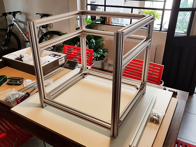
It will have a 300x300mm build platform and 300mm printable height. 3030 Rexroth extrusions and fully enclosed. Not actively heated through.The thing is, when assembling the frame got the idea of removing the top front extrusion.
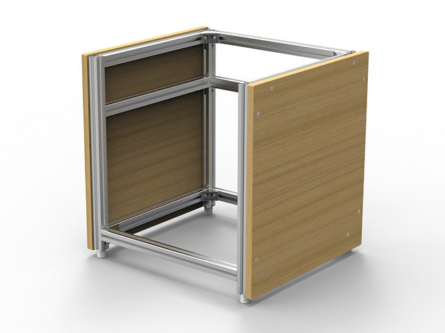
The frame itself is almost rock solid. Yes, almost, because of the part I left free. If I push the corners with some force, it bends a bit, like 1mm. So I thought of adding 2 MDF wood panels to the side. They are 18mm thick.My question is, will these panels do more harm than good? I'm afraid they would be susceptible to humidity and eventually bend the whole frame.
Here are some pics:
https://c1.staticflickr.com/5/4513/37486342492_c51d0845bc_o.jpg
https://c1.staticflickr.com/5/4481/37486341522_66e45b4f1a_o.jpg
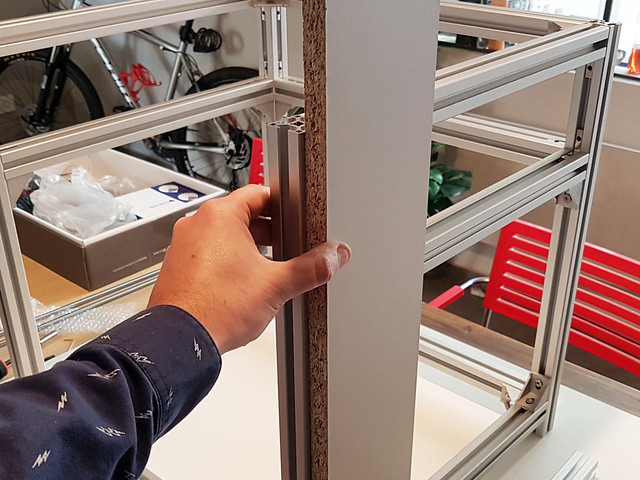
(just to get the dimension, it will actually cover the whole panel and it won't be particle board. MDF instead)As always, any suggestion is much appreciated.
Martin -
This is what I mean:
https://c1.staticflickr.com/5/4443/23665890648_cf7acffb83_o.jpg
-
MDF is reasonable stable but all wood products are hygroscopic. That is to say, they absorb moisture and when wood fibres absorb moisture, they swell. At least with MDF you don't have the grain pattern to worry about so it's unlikely to twist or warp. Thye best thing to do would be to seal it with varnish or some such to prevent moisture ingress.
That should prevent the panels from doing any harm. Whether they do any good is entirely another matter. Personally, I doubt it and the frame really needs to be braced properly across the front.
-
Good idea with the varnish.
Just for fun, I will cut the MDF panels and check if they help or not. Maybe add some thick aluminum 90º joining plates.
There's still time to add the missing extrusion.First time using t-slots as a frame, so testing this is quite enjoyable.
Thanks for the tips.
Martin -
A brace across the top, even a very thin one will make the frame much stiffer than adding boards to the sides. If you think about, applying sideways pressure to one of the top front corners will tend to bend the boards and it won't take much effort. If there was a brace between the two corners, then you have to compress that brace before you see any deflection, and that takes very much more force. Having said that, you might be able to make it "stiff enough".
Is there a particular reason why you don't want a brace across the top? If it's to make it easier to get finished prints off, then maybe you could consider making it removable rather than bolted into position. There are all sorts of ways and means of doing that.
-
I want to use a single polycarbonate sheet that will be bent over the top. It will open like kitchen cabinets with top hinges.
But this can also be done with the top front extrusion installed. The reason is more an aesthetic one really. -
I want to use a single polycarbonate sheet that will be bent over the top. It will open like kitchen cabinets with top hinges.
But this can also be done with the top front extrusion installed. The reason is more an aesthetic one really.In that case I would strongly advise you to fit the top extrusion. Sorry if this sounds harsh but do you want the printer to look good or the prints that it produces to look good?
-
This will have no roof? If you put a top on it, that will "close the circle" and it will be more than rigid enough. If doing so I would not worry about humidity. If left as it is in the picture (just the side panels) in theory it might cause some minor deflections but I would not bet on it.
-
In that case I would strongly advise you to fit the top extrusion. Sorry if this sounds harsh but do you want the printer to look good or the prints that it produces to look good?
This will have no roof? If you put a top on it, that will "close the circle" and it will be more than rigid enough. If doing so I would not worry about humidity. If left as it is in the picture (just the side panels) in theory it might cause some minor deflections but I would not bet on it.
Absolutely right Ian, Top T-slot extrusion installed. Better to go safe.
Please, I don't mind if it sounds harsh, I like honest answers
Sorry for the delay, I wanted to post when I have something else to share or ask, and luckily I have a lot of work at. So this turned out to be a really slow build.
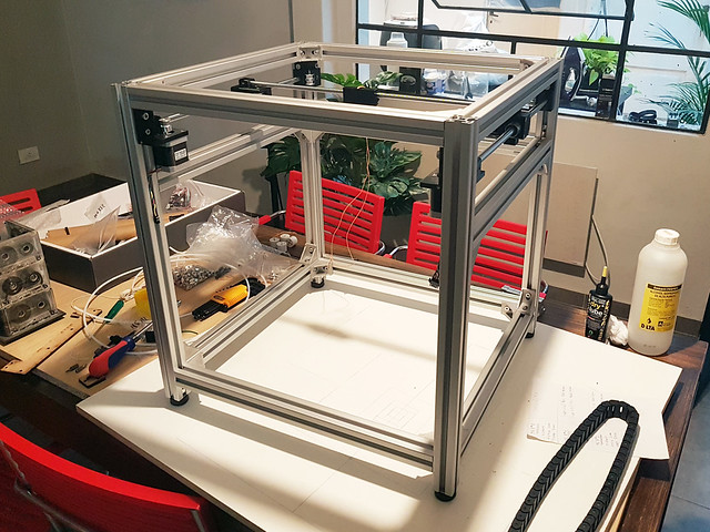
X-Y axis is done and it moves really smooth. At first, the idea was to use graphite self lubricating bushings. But they stall at some places. I can't tell if it was because of the linear guides or because of the printed parts not being perfectly square. End up using LMU bearings. 10mm for the Y-axis and 8mm for the X-axis. For Z 12mm.The X-Y design is based on the Hypercube and HEVO. I love how the belts are arranged.
https://c1.staticflickr.com/5/4572/38406286256_25269dc695_o.jpg
This is the "bed sandwich":
https://c1.staticflickr.com/5/4567/38406285006_138c369ece_o.jpg
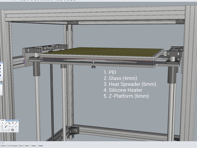
One of the first things that I can't decide is the aluminum thickness. I don't want to have bending problems, but I also don't want a super heavy bed.
So what would be a conservative thickness? I was thinking of 6mm for the z-platform. The heat spreader will have a 4mm glass sitting on top.
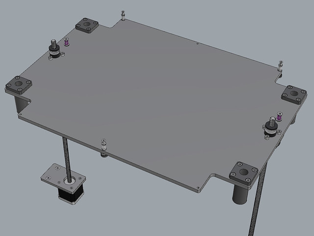
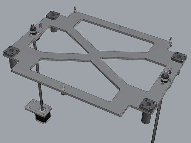
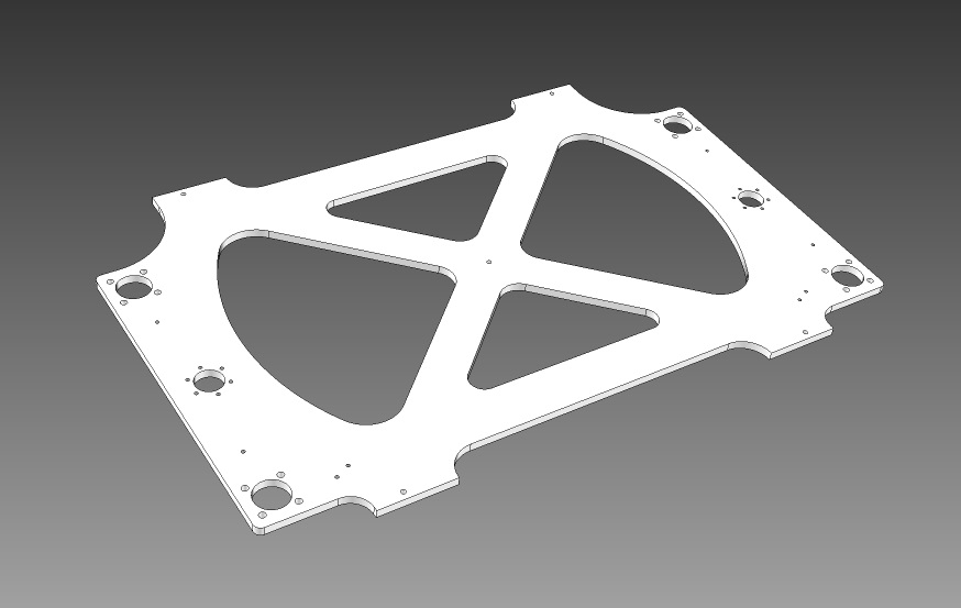
Does it need to be as thick as the z-platform?Also the z-platform design. The idea is to steal some weight without compromising its stiffness, but I don't have much of a reference. So I can't tell how big the holes should be. The platform of the p3 steel is similar in this matter, but it doesn't lift.
Should it be without any holes at all? Any suggestion here is appreciated.Original:
https://c1.staticflickr.com/5/4543/37747525724_c3b1f2b5b5_o.jpg
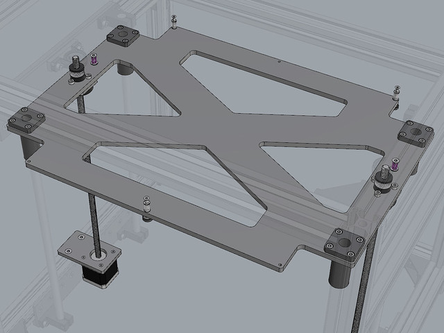
Solid:
https://c1.staticflickr.com/5/4542/38406283736_608847efa7_o.jpg
More hollow:
https://c1.staticflickr.com/5/4550/38406283276_ac7c5b16d2_o.jpg
If someone has any pics or links to share, please do.
Regarding the overall z-design, I would love to follow Ian's (deckingman) advice, that is to go with the 3 leadscrew approach. But I'm having serious trouble sourcing the exact same motor+leadscrew locally and buying from china is not really an option atm. I need to wait until the next year to buy from another country…. customs issues =(
The initial idea was to use two pillow block bearings sitting on top.
Should I discard them? Will they contribute to the over constrain of the bed or they might actually help?And the last thing, 3 or 4 leveling screws? The bed is 315x315mm
For testing, I've laser cut the platform and the heat spreader. When tightening the screws, if I press near the edges, the bed yields a bit and I can't tell if it's normal or it's too much. It sure feels that very little force is required.To sum up...
- thickness of z-platform?
- thickness of heat spreader?
- z-platform design? holow? solid? other?
- Pillow block bearings, use them or not?
- 3 or 4 leveling screws?
-
Hi Martin
It is difficult to say what the best design for a 3D printer is. Everyone sees it with his eyes and tries to build a good printer.
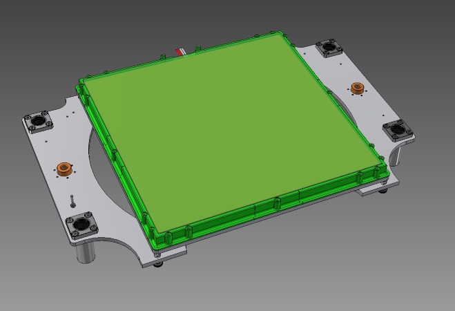
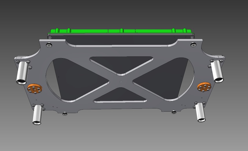
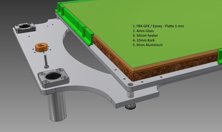
But I can tell you how I built my printer and I am very happy with it.- The guide plate and the construction platform are made of 6mm aluminium.
- I use 4 guide shafts with Ø12mm.
- The building platform is designed with 4 leveling screws.
- My silicone heater is not attached to the aluminium plate, but glued directly to the glass plate. So I have to heat up less mass and it goes much faster.
BerTiNax
-
….........................
Regarding the overall z-design, I would love to follow Ian's (deckingman) advice, that is to go with the 3 leadscrew approach. But I'm having serious trouble sourcing the exact same motor+leadscrew locally and buying from china is not really an option atm. I need to wait until the next year to buy from another country.... customs issues =(
......................................Pretty much any trapezoidal screws will do the job - I'd advise against using 8mm lead though as you'd be looking at 2.5 full steps per 0.1mm which isn't good. So 1, 2 or 4mm lead are all OK although the finer the lead, the less torque you'll need to drive the bed. Also, pretty much any Nema17 with a torque of around 59N.cm upwards would do the job. The biggest issue might be finding a continuous belt long enough. For my 400mm x 400mm bed I managed to get hold of one it was s bit of a struggle. Now that DC42 has got auto bed levelling and motor sync added to the firmware, if I was starting again, I'd probably use 3 motors (one in each screw) instead of the continuous belt.
From an engineering pint of view, the issue with using two screws is that the bed is basically able to pivot about the centre line between the two screws. For sure, it's possible to constrain that pivoting by using linear guides but then you are imparting a twisting force to the guide bearings which isn't what they are designed for. Also trying to get 4 guides perfectly parallel in two plains and at perfect right angle to the bed can be a bit of a challenge. If you take away the tendency for the bed to pivot by supporting it in a plane rather than a line, you instantly overcome those issues and you can use only two guides instead of four. But, hey it's your printer so I'll say no more.
-
Hi Lan
Your explanations are coherent and plausible.
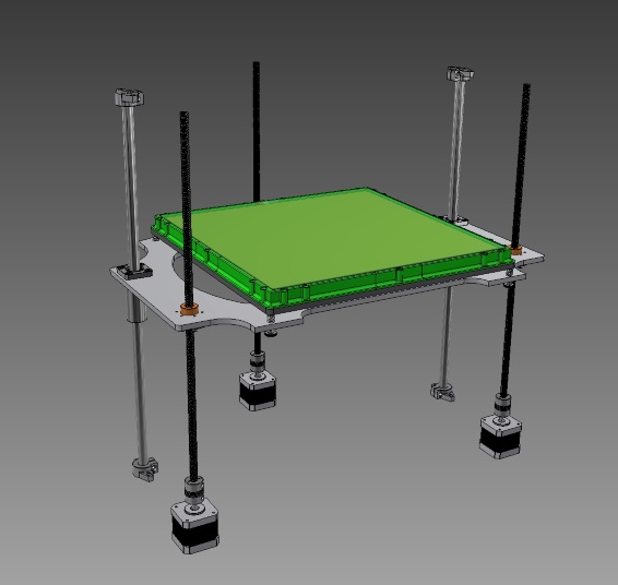
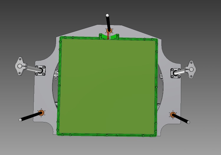
I tried to translate your ideas into a drawing, but I'm not sure if I understood everything correctly.
See photos:…. One more question:
If I have 3 Z-engines, I need the Duex5 expansion board?BerTiNax
-
Hi Bertinax, thank you very much for those pictures, they really help.
Your explanations are coherent and plausible.
I tried to translate your ideas into a drawing, but I'm not sure if I understood everything correctly.
Yes, I understood the same thing.
Pretty much any trapezoidal screws will do the job - I'd advise against using 8mm lead though as you'd be looking at 2.5 full steps per 0.1mm which isn't good. So 1, 2 or 4mm lead are all OK although the finer the lead, the less torque you'll need to drive the bed. Also, pretty much any Nema17 with a torque of around 59N.cm upwards would do the job. The biggest issue might be finding a continuous belt long enough. For my 400mm x 400mm bed I managed to get hold of one it was s bit of a struggle. Now that DC42 has got auto bed levelling and motor sync added to the firmware, if I was starting again, I'd probably use 3 motors (one in each screw) instead of the continuous belt.
From an engineering pint of view, the issue with using two screws is that the bed is basically able to pivot about the centre line between the two screws. For sure, it's possible to constrain that pivoting by using linear guides but then you are imparting a twisting force to the guide bearings which isn't what they are designed for. Also trying to get 4 guides perfectly parallel in two plains and at perfect right angle to the bed can be a bit of a challenge. If you take away the tendency for the bed to pivot by supporting it in a plane rather than a line, you instantly overcome those issues and you can use only two guides instead of four. But, hey it's your printer so I'll say no more.
Belt driven is not really an option. These are the motors with incorporated leadscrew that I have:
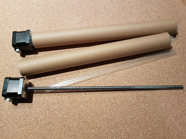
https://www.robotdigg.com/product/557/Nema17-linear-stepper-with-Tr8*4-leadscrewThey are TR84. Not as fast as a TR88 but with better resolution. TR82 or TR81 might be a better choice but I was afraid they would be too slow.
Not trying to be hard headed here, I get what Ian is saying and it sounds like the correct way to go, but when I claim that in this country is expensive I mean it. For example, if I want to buy here a very similar leadscrew+motor it costs u$s 81 (yes! almost the triple). No way if I can buy them from robotdigg for u$s35. I won't lie, I'm pissed for not asking here before, I would have bought 3 instead of 2 =(
So, in order to be able to fix this
maybefuture to be mistake…. what I might do is make the Z-platform ready to work with 3 leadscrews. But first try to make it work with 2 leadscrews.Thank you all for the help.
Martin -
…. One more question:
If I have 3 Z-engines, I need the Duex5 expansion board?If you have 3 Z motors and you want to control them independently for bed levelling, and assuming just 1 extruder, then you need a total of 6 drivers. So you need 1 more then the basic Duet provides. Here are some options:
1. DueX5 board, This will leave you 4 drivers spare for future expansion e.g. Diamond hot end or IDEX.
2. DueX2 board. This will leave you 1 driver spare for future expansion, enough for a Cyclops or Chimera hot end or a 2-into-1 filament switcher.
3. Add a single Pololu external driver as described at https://duet3d.com/wiki/Using_external_drivers and use it to drive the extruder.
-
Hi Lan
Your explanations are coherent and plausible.
I tried to translate your ideas into a drawing, but I'm not sure if I understood everything correctly.
See photos:
…...............................BerTiNax
Yes, that's the idea. It'll be better still if you can arrange the linear guides so that they are on opposite corners, say front left close to the screw and rear right, or front right and rear left. The reason being that if the guides are close to the edge, then any play in the guides will be the worse case for the bed and should be minimal. So say for example that there is 0.1 mm play in the guide or flex in the guide rod, and the guide is close to a corner then the maximum XY play on the bed will be that amount (0.1mm). If however the guides are close to the centre of the bed, then any play or flex in the rods will be magnified at the corners so that 0.1mm might become 1mm at the edge.
I'm being pedantic and what you have shown should work well enough though.