Duet 2 WiFi - wich expansion pins as GIPO?
-
My dearest co-printers, i have a (maybe simple) question:
Which pins on a Duet 2 WiFi expansion-header can be used for GIPO-pins?
Of course its the remaining five heaters (no probs there). I need up to 8 additional pins for controlling relays. Is it possible to use the EN-pins of the unused extruders?If yes, please help me with the definition of the following. How do i clear and redefine an extruder pin correctly?
M950 P8 C"^exp.e5_en" ; printstate redMany thanks in advance and greetings from stormy gemany,
Julien -
@zipzap said in Duet 2 WiFi - wich expansion pins as GIPO?:
Is it possible to use the EN-pins of the unused extruders?
Ian (from stormy England!)
-
@droftarts
Well, thats too bad (for now).
So I2C-expander it is, for the next project.Thanks for the useful information.
/Julien
-
@zipzap Did you mean endstop pins, or stepper driver enable pins? You
can use the endstop pins, butcan't use the stepper driver enable pins (not an available pin) or endstop pins (input only). If you don't need PWM (and the enable/endstop pins wouldn't be PWM anyway), there areplenty ofother pins you can use on the expansion header to driverelayslow current SSR/MOSFETs. If you need additional PWM outputs, a DueX or SX1509 port expander would offer them, see https://docs.duet3d.com/en/User_manual/Connecting_hardware/IO_additional_IOIan
-
Sorry for the late reply.
Yes, i only need IOs for relays, so no PWM.
The documentation said that every other pin (for ex. endstops) are just inputs? If they could be configured as outputs, than its easy game.Would you be so kind to point out which pins can be used as outputs (for relays) and how to configure them? That would be a huge help.
/Julien
-
@zipzap I've updated the I/O pin table here https://docs.duet3d.com/en/Duet3D_hardware/Duet_2_family/Duet_2_WiFi_Ethernet_Hardware_Overview#inputoutput with a column for I/O capability. So long as your relays can be triggered by 3.3V (and very low current, ie an SSR, MOSFET or transistor), you should be able to use any of the pins with 'output' or 'yes' in the 'Input/Output?' column. Also note that there is no protection on all output pins. Read the notes too, though.
So you should be able to use: bedheat, e[0-1]heat, exp.heater[3-7], fan[0-2], pson, zprobe.mod, exp.e[2-6]stop, exp.pb6, spi.cs1, spi.cs2, spi.cs3, spi.cs4, spi.cs5, spi.cs6, spi.cs7, spi.cs8, connlcd.encb, connlcd.enca, connsd.encsw, urxd0, utxd0
Note that bedheat (VIN), e[0-1]heat (VIN) and fan[0-2] (selectable VIN/5V/external supply) outputs are NOT 3.3V.
To use a pin, see https://docs.duet3d.com/en/User_manual/Connecting_hardware/IO_GPIO
This shows an example for a PWM pin. For non-PWM, define the pin as an GPIO port with M950, then turn it off/on with M42:
M950 P0 C"exp.e2stop"  ; allocate GPIO port 0 to e2stop on expansion connector
...
M42 P0 S1  ; set GPIO port 0 on.
M42 P0 S0  ; set GPIO port 0 off.
Ian
-
This is just awesome!
The current of the pins should pose no real problem, since the inputs of the relayboards are conneted via isolators - i just need to check, if 3V3 is sufficient.I will give an update, when i did the wiring.
/Julien
-
"Also note that there is no protection on all output pins. "
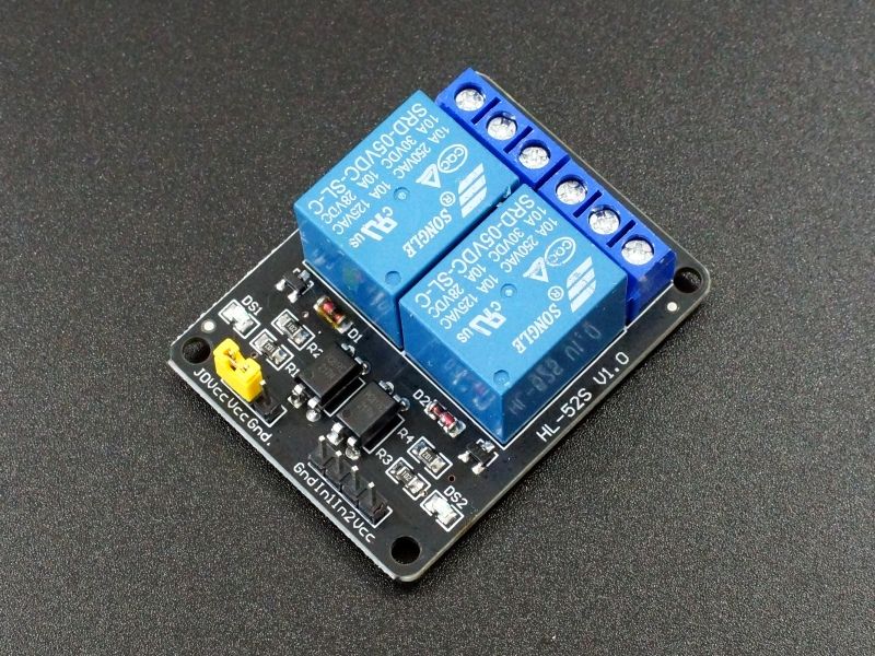
Does this mean any relay connected to expansion headers must have optocoupler isolation? I have this relay which doesn't seem to have an optocoupler but states on product description
- The control area and the load area have isolation slots.
- Strong anti-interference ability, using photoelectric isolation and diode freewheeling protection
3.3V 2 Channel 3V Relay Module with Lamp Low Level Trigger 2 Channel Relay Module

I will be using the relay to turn on/off my router and don't I don't want to fry my board

-
@chimaeragh said in Duet 2 WiFi - wich expansion pins as GIPO?:
using photoelectric isolation
That almost sounds like optocoupler isolation.. I'm not sure how you'd check for sure though.
-
Tbh i dont see any isolation on this board aside the "isolation of load and control area" via the relay itself.
You have some flyback diodes on the control side but thats it. the black thingys are just transistors. You could put some 3V3 on the VCC pin, but that has to be at least 500mA or so because it is used to drive the coil of the relay. DO NOT try to drive this board with the IO-pins itself, the current draw is too high.If you want real opto-isolation (which is preferable), you should use a board like this one:

Keep you eyes open for the bulky black boxes with two terminals on each side. Those are the optocouplers.
Greetings from sunny germany,
Julien -
@zipzap Thanks. I have ordered that type. I won't be using the previous relay anymore