1LC v1.1 toolboard 5v control
-
@marcossf I suggest a 4.7mH inductor rated at 0.1A or higher between the OUT1_NEG pin and the negative motor terminal, and then a 10uF 25V capacitor connected in parallel with the motor. Don't use the capacitor without also using the inductor. Set the PWM frequency to 65000 in the M950 command.
-
@dc42 OK, thank you.
I'll prototype a small PCB to fit these components inside printheads, and test it.
I guess with this board between the 1LC and the motor it means we can use M42 S1 and will send full 12V to Out1 without any problems. -
@marcossf said in 1LC v1.1 toolboard 5v control:
@dc42 OK, thank you.
I'll prototype a small PCB to fit these components inside printheads, and test it.
I guess with this board between the 1LC and the motor it means we can use M42 S1 and will send full 12V to Out1 without any problems.No, you would still need to use M42 S0.4.
OTOH if you use the 6.8V Zener diode in series with the motor instead, you can use M42 S1. As the motor running current is only 40mA, the Zener diodes will only dissipate about 270mW after starting, so it is a reasonable solution. I still suggest you use a 1W Zener diode, not a 400mW one, to better handle the starting current surge.
-
@dc42 OK, so it looks more simple and safe enough use the diode solution then, isn't it?
-
@marcossf said in 1LC v1.1 toolboard 5v control:
@dc42 OK, so it looks more simple and safe enough use the diode solution then, isn't it?
Yes.
-
@dc42 OK, done. We are going to test it.
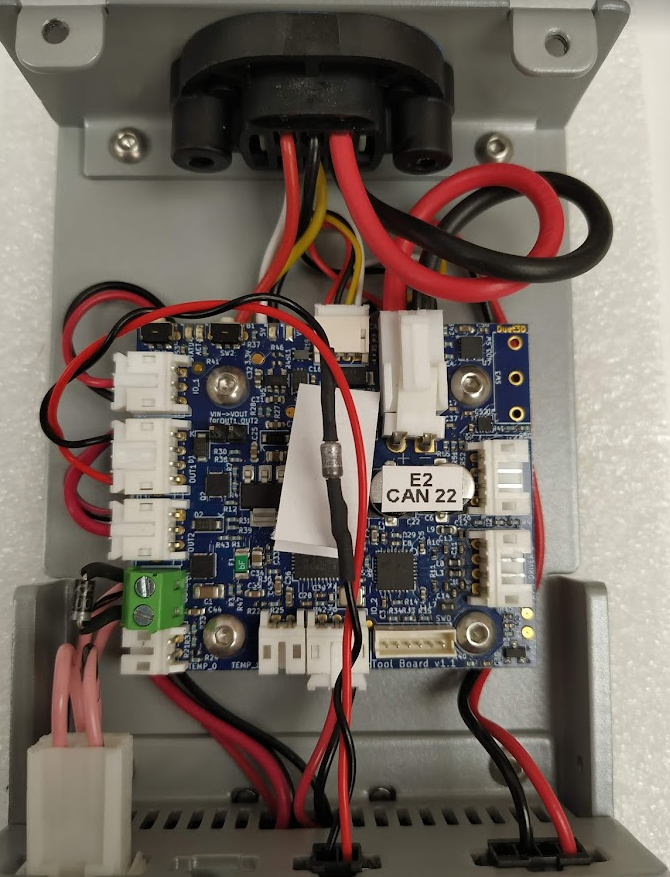
Just for double check, but I think all pins and diodes looks correct, isn't it.

-
@marcossf it looks to me that the connections to the OUT1 port are wrong. Black should go to the OUT1_NEG pin, and red to the VOUT pin.
-
@dc42 OUT 1 block pins are marked like so in the schematics:
GND
+VOUT
out1.tach
out1Do you mean we need to connect +VOUT to the motor positive and out1 to the negative?
It's confuse to me.
-
@marcossf yes. All the outputs on duet boards switch to ground
-
@jay_s_uk OK, thanks Jay.