Use 5v from diffrent source for optical endstops? on duetwifi
-
@StAnZ-007 said in Use 5v from diffrent source for optical endstops? on duetwifi:
@dc42 said in Use 5v from diffrent source for optical endstops? on duetwifi:
e connector or from the expansion connector.
OK, if I use the +5v from pin 1, can I give the power to 5 sensors at the same time on the Pin 1 alone ?
Yes.
-
@dc42 said in Use 5v from diffrent source for optical endstops? on duetwifi:
Yes.
Thanks for your fast answer.
-
So last question,
- Can I connect all my 5v sensor pin to the expansion pin 1 ? => OK, it's clear for me
- Then can I connect all my ground sensor pin to the expansion pin 2 ?
- Then can I connect only signal to X Stop / Y stop / Z stop / E1 ans E2 stop ?
Possible or not ?
Thanks
-
Yes, that's workable.
-
Nice, thanks
-
Hi all,
I also have problems with the optical endstops. The board I have is the Duet2Wifi v1.04 and the endstops are TCST2103 5v optical sensors (https://www.vishay.com/docs/81147/tcst2103.pdf).
VCC is connected to 5v Powersupply
GND to GND on the endstop-pin on the Board
SIG to STP/IN on the endstop-pin on the BoardThe endstops are in the config.g File set to Active-High (M574 X2 Y2 Z2 S1).
If the sensors are triggered, the endstop LEDs on the board go out. But nothing happens in web control -> it shows all sensors are triggered.
No i have measured the sensor signals:
If the sensor is triggered, the output is 4.3v
If the sensor is not triggered, the output is 1.5v, and not 0v or GND...Have I missed something or are my sensors just crap?
Thanks for Help.
-
@KroVex said in Use 5v from diffrent source for optical endstops? on duetwifi:
Hi all,
I also have problems with the optical endstops. The board I have is the Duet2Wifi v1.04 and the endstops are TCST2103 5v optical sensors (https://www.vishay.com/docs/81147/tcst2103.pdf).
VCC is connected to 5v Powersupply
GND to GND on the endstop-pin on the Board
SIG to STP/IN on the endstop-pin on the BoardThe endstops are in the config.g File set to Active-High (M574 X2 Y2 Z2 S1).
If the sensors are triggered, the endstop LEDs on the board go out. But nothing happens in web control -> it shows all sensors are triggered.
No i have measured the sensor signals:
If the sensor is triggered, the output is 4.3v
If the sensor is not triggered, the output is 1.5v, and not 0v or GND...Have I missed something or are my sensors just crap?
Thanks for Help.
The datasheet you linked to is for a bare slotted opto sensor, and as such it does not require 5V. But it does need sufficient forward current in the IR diode to turn the phototransistor fully on. Please provide the schematic of the complete endstop device that uses that sensor, including the values of the resistors on it (there are probably 2 of them).
-
I could not find the original data sheet because the manufacturer (germanreprap.com) has closed its forum.
But maybe the pictures will help:


Three resistors are installed on the back of the sensors: 1002, 1800, 2200
-
Problem solved!
A good tip was that the sensor does not need 5v.
However, the homex / y / z.g files from e.g. G1 H2 Z5 F6000 must be changed to G1 S2 Z5 F6000 (H to S). Now the motors stop when the sensor is triggered.Thx for Help.
-
@KroVex said in Use 5v from diffrent source for optical endstops? on duetwifi:
However, the homex / y / z.g files from e.g. G1 H2 Z5 F6000 must be changed to G1 S2 Z5 F6000 (H to S). Now the motors stop when the sensor is triggered.
Then you must be using quite old firmware.
-
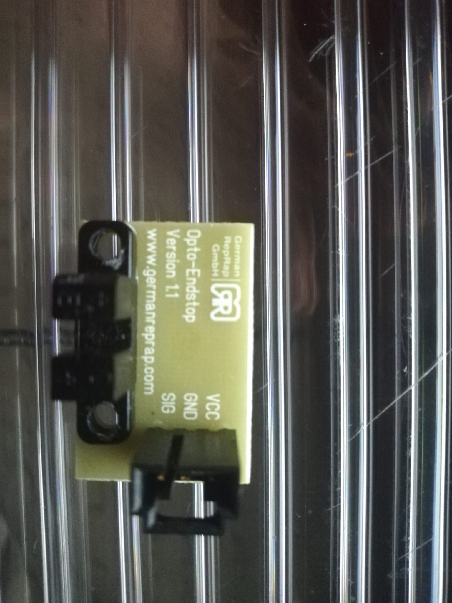
The board I have is the Duet2Wifi v1.02 and the endstops are most likely 5v (see pic), so no luck with that combo. I read somewhere in this forum that it is possible to convert them to 3.3v by adding a resistor. My know-how for these things is close to zero, so could anyone point me to right resistor and what Ohm I need to add (on top of SMD resistor)?
![IMG_20200306_103533[1].jpg](/assets/uploads/files/1583488092969-img_20200306_103533-1-resized.jpg)
-
That endstop may work on 3.3V already. If it doesn't, then I suspect that R1 is the critical component. The picture is a little out of focus, so I can't read the label on it - what is it? Can you measure its value with a multimeter?
-
FWIW, these endstops work fine on 3.3V:
https://www.amazon.com/gp/product/B07JMDLD84/ref=ppx_yo_dt_b_asin_title_o05_s00?ie=UTF8&psc=1
I have two now, and soon three of them, in UMMD.
-
@dc42 said in Use 5v from diffrent source for optical endstops? on duetwifi:
l component. The picture is a little out of focus, so I can't read the label on it - what is it? Can you measure its value with a multimeter?
Hmmm, when I connected them 18 months ago, they did not work...now they do?! Probably my fault. So just for future reference: Optical endstops V1.1 from Trianglelabs are 3.3V tolerant. Yeeeha.
@dc42 thanks for your support (R1 is 470, R6 is 750, all the other 10k Ohm)
@mrehorstdmd thanks for your input as well. On a sidenote: your (coreXY) blog posts are tremendously helpful. So thanks for that too!