Duet2 Wifi and the Sidewinder X1 endstops
-
@t3p3tony Sorry Tony misread it my fault when I sent the M18 then moved the x axis and then run M119 I get " X at min stop" and I used YAT terminal, is that right. That result was from the M574 X1 S1 P"xstop" that you asked me to do.
-
@tisdai ok so it sounds like removing the !^ form the endstop definitions for the type of endstop you have on the X axis works (I am not sure if the same type is fitted to all three axis so you need to test all 3)
-
@t3p3tony Sorry it took so long to reply to you Tony, yes that worked for manually moving all of the axis to the endstop but now none of them move at all when being homed in DWC
-
@tisdai if you manually move them to the center of the machine so nothing is being triggered. then send M119 what do you get?
then send G92 X150 Y150 and try and jog the axis +/- by 10mm. do they move, doe they move in the direction expected?
-
@t3p3tony said in Duet2 Wifi and the Sidewinder X1 endstops:
On the M119 I get the Error message Endstops - X: at min stop, Y: at max stop, Z: at min stop, Z probe: at min stop and when I use the G92 X150 Y150 I get I can get them to move 10mm on the x and y both ways ok but the z will only move on the + and all of them in the right direction.
-
@tisdai ok so the changes we made earlier did not fully sort the problem with the endstops (from you earlier report i thought it had).
So can you confirm if you get a change in the endstop status reported by M119 when the carriage is at the X and Y endstop (lets leave Z out of this for now). Please post both M119 outputs, and confirm what the X and Y M574 definitions are in config.g
-
@t3p3tony said in Duet2 Wifi and the Sidewinder X1 endstops:
M119 result is Endstops - X: at min stop, Y: at max stop, and result is M574 X1 S1 P"xstop" / M574 y1 S1 P"ystop" -
@tisdai and if you move them away from the stops?
-
I found a photo of an Artillery end stop switch that has a manufacturers part number visible, a GL-8H
According to the datasheet for those, they are intended for 12 to 24V operation, with NPN (switch to 0V) outputs.
The switches probably need the power connection (brown or orange) changing from the on board endstop connectors to an external supply.
Refs.
https://www.3djake.com/artillery/x-axis-limit-switch
https://www.aliexpress.com/item/4000139818315.html
https://www.makerstore.com.au/product/elec-gl8h/ -
@t3p3tony They just stay the same Endstops - X: at min stop, Y: at max stop,
Robert J If that is the case then I will either have to buy some new End Stop Limit Switches Suitable for the printer like these, https://www.amazon.co.uk/Printer-Limit-Switch-Suitable-Ender-3/dp/B09161Y56X/ref=pd_sbs_1/262-0198064-0338202?pd_rd_w=n7IMI&pf_rd_p=a3a7088f-4aec-4dbd-97cc-9a059581fe7b&pf_rd_r=SRH1F8T4A74C0AAGK3YG&pd_rd_r=4f8273e1-eae3-49ff-8b46-bf442db76b5e&pd_rd_wg=36QA2&pd_rd_i=B09161Y56X&psc=1
-
Thanks @rjenkinsgb for digging the model number out!
The endstops you linked would be easier wire for sure.
Alternatively you can connect the endstops you have in a similar manner to an NPN zprobe, but the endstop inputs of the duet are only 8V tolerant so you must use a diode for protection:
https://duet3d.dozuki.com/Wiki/Connecting_a_Z_probe#Section_NPN_output_normally_open_inductive_or_capacitive_sensorConnect the power wire of the endstops to VIN (12-24V) and then connect the input wire to the endstop via a diode, similar to this picture:
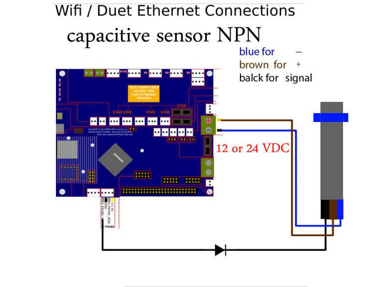
But to the endstop stp pin, not the zprobe input pin. Also note that you must use a diode, no matter what version of the duet, and it must be connected the correct way round.
-
@t3p3tony Thank you very much Tony I will buy the sensors I linked to will be easier all round, You have a great forum here with some very helpful members willing to take the time out to help others. Thanks to you too Richard for the info on the model number and info on the voltages helped me make my mind up a lot quicker.
-
@t3p3tony I bought those limit switches I linked to here
They are working ok I just had to alter the M574 code for the Endstops by adding ! to the X and Y Stop section and switch the wires around on the connectors to match the Duet2 wiring diagram.
M574 X1 S1 P"!xstop"
M574 Y2 S1 P"!ystop"
M574 Z1 S1 P"zstop"Thanks for your help appreciate it.