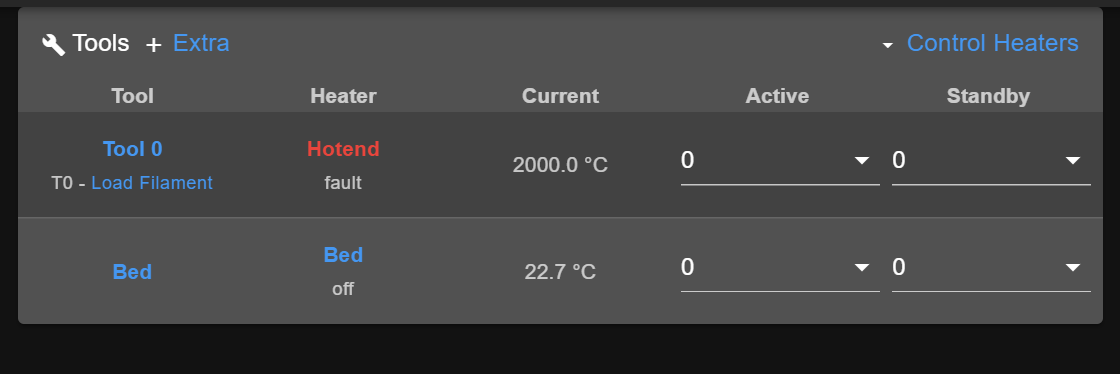
After updating to 3.4.0beta2: faulty heater 1, -273.1C.
-
@dc42 said in After updating to 3.4.0beta2: faulty heater 1, -273.1C.:
@empi00 I am wondering whether it just needs different calibration. Please can you:
- Send M308 S1 (assuming the tool board thermistor is Sensor 1) and record the result, in particular the H and L values.
- Send M122 B121 and record the reported VIN value
- Switch the tool board firmware to 3.4beta2.
- Send M308 S1 again, check that it reports the same H and L
- Send M122 and check tna the reported VIN value is the same as before
- Run the calibration procedure described at https://duet3d.dozuki.com/Wiki/Calibrating_thermistor_and_PT1000_readings on the tool board thermistor input. If it's tricky to do the short-circuit calibration test, just do the open-circuit calibration, which should be sufficient to correct the reading at room temperature.
- Send M308 S1 again to see the new H and L values
- Check whether the readings are now correct.
I am assuming that you do not have H and L parameters in your M308 commands in config.g, so it will use the values stored in NVRAM.
Hi dc42, this is for that.
-
@serge what were the values reported by M308 S1 before and after you ran the M308 S1 H999 command?
-
@dc42 H-8 L-13
after the calibration, H51 L-13, but i can't calibrate with M308 S1 L999 -
@serge said in After updating to 3.4.0beta2: faulty heater 1, -273.1C.:
@dc42 H-8 L-13
after the calibration, H51 L-13, but i can't calibrate with M308 S1 L999Thanks. Do you mean you can't calibrate because you can't easily short the pins TEMP0 together?
-
@dc42 I went through your Procedure, I hope it helps:
Send M308 S1 (assuming the tool board thermistor is Sensor 1) and record the result, in particular the H and L values.
Sensor 1 (Hotend) type PT1000 using pin 121.temp0, reading 20.8, last error: sensor not ready, R:2200.0 L:-8 H:-12Send M122 B121 and record the reported VIN value
VIN: 24.4VSwitch the tool board firmware to 3.4beta2.
Send M308 S1 again, check that it reports the same H and L
Sensor 1 (Hotend) type PT1000 using pin 121.temp0, reading 6.6, last error: sensor not ready, R:2200.0 L:-8 H:-12Send M122 and check tna the reported VIN value is the same as before
VIN: 24.3VRun the calibration procedure described at https://duet3d.dozuki.com/Wiki/Calibrating_thermistor_and_PT1000_readings on the tool board thermistor input. If it's tricky to do the short-circuit calibration test, just do the open-circuit calibration, which should be sufficient to correct the reading at room temperature.
H: works
L: M308 S1 L999
Error: M308: Computed correction is not valid. Check that you have placed a jumper across the thermistor input.(I did jumper the input and I verified that it shorts correctly)
Send M308 S1 again to see the new H and L values
Sensor 1 (Hotend) type PT1000 using pin 121.temp0, reading 2000.0, last error: short-circuit in sensor, R:2200.0 L:-8 H:52Check whether the readings are now correct.
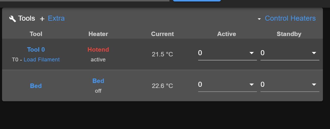
NO, the temperature actually dropped by 2 degrees.
-
@dc42 one more point: I did downgrade the 1LC V1.1 back to 3.3 and repeated the calibration procedure, worked without issues.
-
@pixelpieper thanks for that data. That gives me something to work on.
-
@dc42 said in After updating to 3.4.0beta2: faulty heater 1, -273.1C.:
@pixelpieper thanks for that data. That gives me something to work on.
I don't know if more information is needed, but I would also like to confirm the temperature problem .
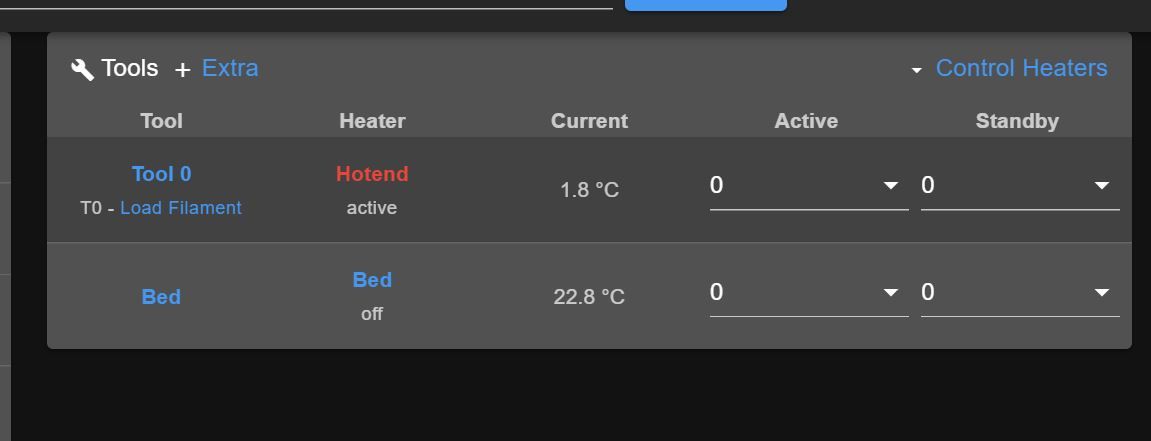
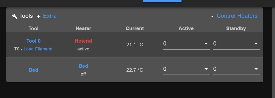
recorded temperature at room temperature - RRF3.4b2

recorded temperature after change to RRF3.3

I performed the following actions
1.Send M308 S1 (assuming the tool board thermistor is Sensor 1) and record the result, in particular the H and L values.
2.Send M122 B121 and record the reported VIN value
3.Switch the tool board firmware to 3.4beta2.
4.Send M308 S1 again, check that it reports the same H and L
5.Send M122 and check tna the reported VIN value is the same as before
6.Run the calibration procedure described at https://duet3d.dozuki.com/Wiki/Calibrating_thermistor_and_PT1000_readings on the tool board thermistor input. If it's tricky to do the short-circuit calibration test, just do the open-circuit calibration, which should be sufficient to correct the reading at room temperature.
7.Send M308 S1 again to see the new H and L values
8.Check whether the readings are now correct.1.Send M308 S1 (assuming the tool board thermistor is Sensor 1) and record the result, in particular the H and L values.
M308 S1
Sensor 1 (Hotend) type Thermistor using pin 121.temp0, reading 21.4, last error: success, T:100000.0 B:4138.0 C:0.00e+0 R:2200.0 L:-7 H:-12
2.Send M122 B121 and record the reported VIN value
M122 B121
Diagnostics for board 121:
Duet TOOL1LC firmware version 3.3 (2021-06-15 16:12:58)
Bootloader ID: SAMC21 bootloader version 2.3 (2021-01-26b1)
...........
VIN: 24.9V
3.Switch the tool board firmware to 3.4beta2.
4.Send M308 S1 again, check that it reports the same H and L
M308 S1
Sensor 1 (Hotend) type Thermistor using pin 121.temp0, reading 3.1, last error: sensor not ready, T:100000.0 B:4138.0 C:0.00e+0 R:2200.0 L:-7 H:-12
5.Send M122 and check tna the reported VIN value is the same as before
m122 b121.0
Diagnostics for board 121:
Duet TOOL1LC firmware version 3.4.0beta2 (2021-08-03 10:00:09)
Bootloader ID: SAMC21 bootloader version 2.3 (2021-01-26b1)
...................
VIN: 24.9V
6.Run the calibration procedure described at https://duet3d.dozuki.com/Wiki/Calibrating_thermistor_and_PT1000_readings on the tool board
thermistor disconnected

M308 S1 H999
Measured H correction for port "121.temp0" is 47
jumper across each thermistor input

cM308 S1 L999
Error: M308: Computed correction is not valid. Check that you have placed a jumper across the thermistor input.ode_text
7.Send M308 S1 again to see the new H and L values
M308 S1
Sensor 1 (Hotend) type Thermistor using pin 121.temp0, reading 21.4, last error: success, T:100000.0 B:4138.0 C:0.00e+0 R:2200.0 L:-12 H:47
8.Check whether the readings are now correct
reading at room temperature seems to be OK.

but how i can be sure about high temps?
-
@cadetc thanks for your test results. I recommend you revert the tool board firmware to 3.3 and recalibrate, until I have identified and fixed the problem. You can continue running 3.4beta2 on the main board.
-
@dc42 said in After updating to 3.4.0beta2: faulty heater 1, -273.1C.:
@cadetc thanks for your test results. I recommend you revert the tool board firmware to 3.3 and recalibrate, until I have identified and fixed the problem. You can continue running 3.4beta2 on the main board.
so if iI go back to 3.3 for toolboard and if in config-override.g i'll put this line then i should be OK? (original factory values before calibration done in RRF3.4b2)
M308 S1 L-7 H-12Hot to store this back in to nonvolatile memory?
-
@cadetc said in After updating to 3.4.0beta2: faulty heater 1, -273.1C.:
Hot to store this back in to nonvolatile memory?
If you ran M308 S# H999 (where # is the sensor number) then it has already been stored. Similarly for M308 S# L999.
-
@CadetC @pixelpieper @Serge I am still trying to determine why I don't see this issue on my tool boards. Please can you each run M122 B# where # is the tool board number, and tell me what bootloader version it reports.
-
@dc42 said in After updating to 3.4.0beta2: faulty heater 1, -273.1C.:
@CadetC @pixelpieper @Serge I am still trying to determine why I don't see this issue on my tool boards. Please can you each run M122 B# where # is the tool board number, and tell me what bootloader version it reports.
M122 B121 Diagnostics for board 121: Duet TOOL1LC firmware version 3.3 (2021-06-15 16:12:58) Bootloader ID: SAMC21 bootloader version 2.3 (2021-01-26b1 -
@cadetc thanks, it's not the bootloader version then.
@CadetC @pixelpieper @Serge I have identified a possible cause of this issue. Please try the new tool board firmware at https://www.dropbox.com/sh/cq7q3g8coymo9s3/AABtPYEzV1_unETpKEMPInSia?dl=0. If with this version you find the temperature error is much reduced, then please re-run the temperature calibration and report the new H and L values. If you still get large errors with this version, then just revert the tool board firmware to 3.3.
-
@dc42 I installed the firmware, I get a temperature rise from 35 to arround 65 degrees with the 3.3 H & L values. When trying to calibrate:
M308 S1 H999
Measured H correction for port "121.temp0" is 48M308 S1 L999
Error: M308: Computed correction is not valid. Check that you have placed a jumper across the thermistor input. -
@dc42 For the bootloader version:
M122 B121Diagnostics for board 121:
Duet TOOL1LC firmware version 3.3 (2021-06-15 16:12:58)
Bootloader ID: SAMC21 bootloader version 2.3 (2021-01-26b1)
Never used RAM 2460, free system stack 2789 words
Tasks: Move(notifyWait,0.0%,153) HEAT(delaying,0.2%,117) CanAsync(notifyWait,0.0%,65) CanRecv(notifyWait,0.0%,76) CanClock(notifyWait,0.0%,65) ACCEL(notifyWait,0.0%,61) TMC(delaying,2.8%,57) MAIN(running,92.0%,352) IDLE(ready,0.0%,27) AIN(delaying,4.9%,142), total 100.0%
Last reset 00:00:46 ago, cause: software
Last software reset time unknown, reason: AssertionFailed, available RAM 3392, slot 1
Software reset code 0x0120 ICSR 0x00000000 SP 0x2000415c Task Freestk 129 bad marker
Stack: 00000544 00022ffc 00019b65 20003134 00016cff 20003134 000163d1 20000ed0 00000000 00000001 00008275 200071c8 200071c8 200071e0 00000000 20000f50 00011647 000223b8 00022474 00021ac8 00019b05 200071c8 200071c8 20000f50 000083ed 200071d8 000009c7
Driver 0: position 0, 655.0 steps/mm, standstill, SG min/max 0/0, read errors 0, write errors 1, ifcnt 71, reads 23059, writes 12, timeouts 0, DMA errors 0, steps req 0 done 0
Moves scheduled 0, completed 0, in progress 0, hiccups 0, step errors 0, maxPrep 0, maxOverdue 0, maxInc 0, mcErrs 0, gcmErrs 0
Peak sync jitter -2/8, peak Rx sync delay 193, resyncs 0/0, no step interrupt scheduled
VIN: 24.4V
MCU temperature: min 46.9C, current 46.9C, max 47.2C
Ticks since heat task active 176, ADC conversions started 46170, completed 46170, timed out 0, errs 0
Last sensors broadcast 0x00000006 found 2 181 ticks ago, loop time 0
CAN messages queued 590, send timeouts 0, received 436, lost 0, free buffers 37, min 37, error reg 110000
dup 0, oos 0/0/0/0, bm 0, wbm 0, rxMotionDelay 0
Accelerometer detected: yes, status: 00
I2C bus errors 0, naks 0, other errors 0 -
@dc42
@pixelpieper said in After updating to 3.4.0beta2: faulty heater 1, -273.1C.:I installed the firmware, I get a temperature rise from 35 to arround 65 degrees
I my case tool temperature reported in 3.3 =20.4C
after 3.4b2-1 installed reported temperature dropped to 0.6C - and is very unstable - jumping from 0.5 to 2.5C - L &H values unchanged - same as in 3.3After calibration done in 3.4b2-1 :
H- 48
L- calibration -errorM308 S1 L999 Error: M308: Computed correction is not valid. Check that you have placed a jumper across the thermistor input.so I reverted back to 3.3 and "old" L&H values
-
@pixelpieper said in After updating to 3.4.0beta2: faulty heater 1, -273.1C.:
@dc42 I installed the firmware, I get a temperature rise from 35 to arround 65 degrees with the 3.3 H & L values. When trying to calibrate:
M308 S1 H999
Measured H correction for port "121.temp0" is 48M308 S1 L999
Error: M308: Computed correction is not valid. Check that you have placed a jumper across the thermistor input.Thanks, still not right then. Please share your confif.g file.
-
@dc42 Here you go:
;; system and network -------------------------------------- M550 PMunin ; hostname M552 S1 P"M" M586 P2 S1 R23 T0 ; enable telnet M586 P1 S1 T0 ; enable ftp ;M555 P2 ; set Marlin output mode G21 ; millimeter units G90 ; absolute tool coordinates M83 ; relative extruder coordinates ; constants of the device geometry global max_x = 252 global max_y = 256 global z_stop_x = {global.max_x-24.5} global z_stop_y = {global.max_y-3} global mag_probe_x = 51 global mag_probe_y = {global.max_y} global mag_probe_z = 1.7 global QGL_probe = 2 ; 1 = inductive, 2 = magnet ; speed & acceleration settings mm/min global xy_accel = 2000; global z_accel = 1000; global xy_speed = 60000; global z_speed = 6000; ;; enable paneldue ;M575 P1 B57600 S1 ; Mini 12864 M918 P2 E-4 R3 C100 ; Enable FYSetc Mini 12864 M150 X2 R255 U255 B255 S3 ; FYSETC Neopixel background: set all 3 LEDs to white ;M950 P0 C"io3.out" Q500 ; generate PWM pin (red on mini12864 V1.2) ;M42 P0 S0 ; turn off ;; geometry ------------------------------------------------ M667 S1 ; corexy mode M208 X0 Y0 Z-3 S1 ; S1 = set axes minima M208 X{global.max_x} Y{global.max_y} Z235 S0 ; S0 = set axes maxima M557 X20:240 Y25:235 S20 ; configure z probing grid for mesh compensation ;M98 P"/macros/zprobe/use_mfast.g" ;M98 P"/macros/zprobe/use_ifast.g" ; mechanical switch M558 K0 P5 C"io4.in" I0 H0 R0.1 F1200 T99999 A1 B1 G31 K0 X0 Y0 ; inductive probe M558 K1 P8 C"121.io2.in" I1 A3 H12 R0.1 F800 T99999 A1 B1 G31 P1000 K1 X0 Y25 Z0.318 ; magprobe M558 K2 P8 C"121.IO1.in" F150 T1000 H2 G31 P1000 K2 X-2.5 Y38.5 Z7 ;; drive --------------------------------------------------- ;; Motor layout: ;; E0 E1 ;; YB XA ;; Z2 Z3 ;; Z0 Z1 M584 X2 Y1 Z5:4:3:6 E121.0 ; motor bindings ;;M574 X2 Y2 Z0 S1 ; endstops M574 X2 S1 P"!io6.in" ; X min active low endstop switch M574 Y2 S1 P"!io5.in" ; Y min active low endstop switch ;M574 Z1 S1 P"io4.in" ; Z min active high endstop switch M671 X-65:-65:315:315 Y-10:325:325:-10 S20 ; Z leadscrews positions M569 P0 S1 ; E0 motor direction M569 P1 S0 ; Y motor direction M569 P2 S1 ; X motor direction M569 P5 S0 ; ZFL motor direction M569 P4 S1 ; ZBL motor direction M569 P3 S0 ; ZBR motor direction M569 P6 S1 ; ZFR motor direction M84 S3600 ; motor idle timeout M906 I50 ; motor idle current percentage M350 X16 Y16 Z16 E16 I1 ; set microstepping M92 X80 Y80 Z400 E655 ; set microsteps per mm ;; velocity, acceleration, and current settings are in these macros M98 P"/macros/drive/xy_fullcurrent.g" M98 P"/macros/drive/z_fullcurrent.g" M98 P"/macros/drive/e_fullcurrent.g" ;; firmware retraction ------------------------------------- ;; Choose one as your default: ;M98 P"/macros/retraction/quiet_nozhop.g ;M98 P"/macros/retraction/quiet_zhop.g M98 P"/macros/retraction/pa_nozhop.g" ;M98 P"/macros/retraction/pa_zhop.g" ;; thermal ------------------------------------------------- ; Sensors -------------------------------------------------- M308 S0 P"temp0" Y"thermistor" T100000 B3950 A"Bedmat"; configure sensor 0 as thermistor on pin temp0 M308 S1 P"121.temp0" Y"pt1000" A"Hotend" ; configure sensor 1 as thermistor ;M308 S1 P"e0temp" Y"thermistor" T100000 B3950 A"Hotend" M308 S2 P"121.temp1" Y"thermistor" T100000 B3950 A"Chamber" ;Chamber fan M308 S3 Y"mcu-temp" A"Board" ;M308 S4 P"e1temp" Y"thermistor" T100000 B3950 A"Bedplate" ; Heaters -------------------------------------------------- ;Bed M950 H0 C"out0" T0 ; create bed heater output on out0 and map it to sensor 4 M950 H1 C"121.out0" T1 ; create nozzle heater output on e0heat and map it to sensor 1 M140 H0 ;PID Settings M307 H0 A301.0 C845.3 D1.4 S1.00 V23.6 B0 M307 H1 A482.6 C291.7 D5.5 S1.00 V23.6 B0 ;V6 ; Monitors & Limits ;M143 H0 P1 T0 A2 S130 C0 ; Regulate (A2) bed heater (H0) to have pad sensor (T0) below 110°C. Use Heater monitor 1 for it ;M143 H0 P2 T0 A0 S135 C0 ; Fault (A0) bed heater (H0) if pad sensor (T0) exceeds 135°C. Use Heater monitor 2 for it M143 H0 P0 S120 ; Set bed heater max temperature to 120°C, use implict monitor 0 which is implicitly configured for heater fault M143 H1 S400 ; set temperature limit for heater 1 to 275C M912 P0 S-8 ;MCU tempurature sensor correction ;; fans ------------------------------------------------- ;Parts M950 F0 C"121.out2" Q500 M106 P0 S0 B0.1 L128 C"Part" ; part fan ;Hot End M950 F1 C"121.out1" Q500 M106 P1 T60 H1 C"Hotend" ; hotend fan PWMED DOWN ;Board cooling M950 F2 C"out3" Q500 M106 P2 S0.5 C"Board"; On when MCU temp (H3) reaches 45C ;H2 L180 X255 T30:50 ;M106 P2 S255 C"Board" M950 F3 C"out4" Q500 M106 P3 S0 C"Exhaust" ;; tools --------------------------------------------------- M563 P0 D0 H1 ; bind tool 0 to drive and heater G10 P0 X0 Y0 Z0 ; tool offset G10 P0 S0 R0 ; tool active and standby temp T0 ; activate tool 0 ;; Accelerometer M955 P121.0 I05 ;; filament sensor --------------------------------------- ;M591 D0 P3 C3 S0 R75:125 L24.8 E3.0 ; Duet3D rotating magnet sensor for extruder drive 0 is connected to E0 endstop input, enabled, sensitivity 24.8mm.rev, 85% to 115% tolerance, 3mm detection length ;M591 P5 C"e0stop" S1 ; Laser Filament Monitor ;; Buttons on the toolboard M950 C"121.button0" J0 M950 C"121.button1" J1 M581 P0 T2 M581 P1 T3 -
@pixelpieper thanks.
I've run your configuration on my bench system and I still don't get a significant error in the temperature reading. A 1K resistor (simulating a PT1000 sensor) gives me a reading of -1.4C which is close enough to 0C. I re-ran calibration and ended up with H-7 L-13 which are within the normal range. So the issue doesn't appear to be configuration-dependent.
Please run the following two commands on your system, with firmware 3.4.0beta2 installed on the tool board, and report the responses:
m122 b121 p1007 a{0x806020}
m122 b121 p1007 a{0x4200442c}