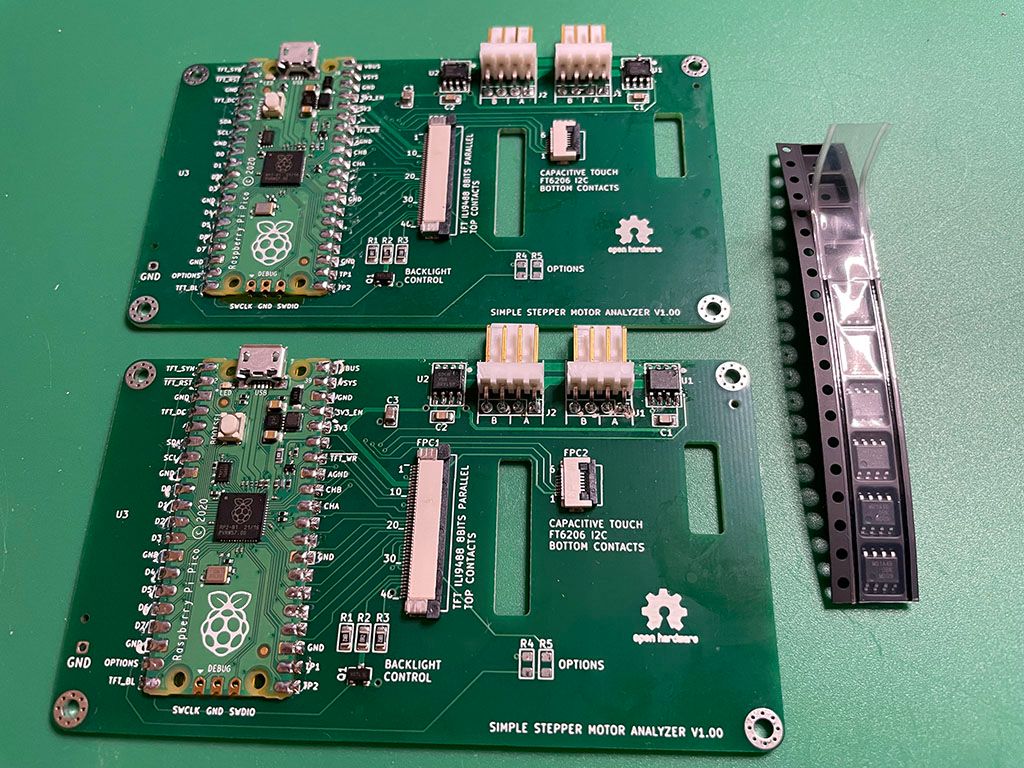
Anybody wants a stepper motor analyzer?
-
Hey all, just a quick update. I ran out of connectors, if you still want an analyzer I still have 3 but won't have any connectors to make jumpers. I have another batch on the way that I should see in January.
-
@th0mpy said in Anybody wants a stepper motor analyzer?:
that I should see in January.
...which year?

It's frightening to see the supply-chains crash. Experts say, the shortage will last till end '22.... -
@o_lampe It's crazy. The original sensors that I used, went away at a blink, then thee ones that @rjenkinsgb pointed out just magically appeared.. It's a crap shoot really.
The boards that I've been having made are pretty reliable, they have about a 3 week turnaround and it's stayed pretty consistent.
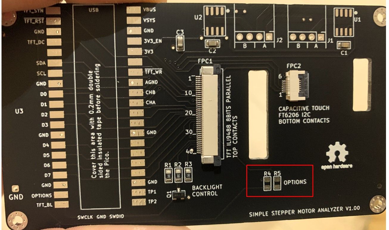
That said, I am working to publish my updates to the analyzer, I worked with @zapta and I will re-host my fork when I get it cleaned up. The benefit here is that we can start adding a lot more options for sensors, without too much rework in the code, we can just add the sensor specs and set the solder jumper as necessary. I'm hoping that we can eventually get to a point where we can reliably source just one sensor and standardize that. In the meantime we should be able to really get some good testing on whatever the market has available.
-
@th0mpy said in Anybody wants a stepper motor analyzer?:
and set the solder jumper
Just a minor idea, If you will use a standard footprint and zero ohms resistors, SMD services such as JLCPCB will be able to populate them as well.
-
@zapta Fair point
 I did it with solder jumpers to make it easier if anyone wanted to change things in the future. I have to touch each one anyway, and it only takes 2 seconds to do, so for now I'm good with it.
 -
@th0mpy said in Anybody wants a stepper motor analyzer?:
In the meantime we should be able to really get some good testing on whatever the market has available.
Right! There's a good side in everything....the suppliers can sell their dust-collectors (for a fortune
 ) and we get a greater knowledge
 -
Do the jumpers come here? Or do you need another board

-
@dogma2k Which chip are you going to use?
-
Just received & fitted the current sensor ICs from Mouser.
I still have to install the programming stuff, but once I have that set up and assuming the boards work OK, I'll let some of the spare current sensors & PCBs go at cost, if anyone in the UK / Europe wants them.

-
@rjenkinsgb which sensors are that now?
-
@rjenkinsgb said in Anybody wants a stepper motor analyzer?:
The TMCS1101A4BQDT from Mouser.
I've now got the boards programmed.
The display is showing continuous slight variations in the current with nothing connected so I'd guess the sensors are giving a slight "noise" output, +/- a few tens on mA reading while nothing is connected.And I've just realised I do not have any suitable connectors to intercept the stepper motor end of the machine cables!
(The Duet end is fully harnessed & laced so it's not practical to lift single connectors at the board).
I want to be able to connect at the motors anyway, as I'm using E3D toolboards so the board connections for the direct tools are totally different from the axis motor feeds.
I'll see if I can find stepper extensions with appropriate connectors that I can hack up..

-
@rjenkinsgb Which connectors do you need? I just received a my order of the WURTH connectors (similar to the Duet 5+ or Duet 2). They look similar to yours on the board. I could send over a couple if you're willing to wait and part with some beer money.

-
@th0mpy
That's a good question at the moment there is almost nothing to buy, so I'll take the one that is available again first. So ACS70331EOLCTR-2P5B3 or TMCS1101A4BQDT -
@th0mpy said in Anybody wants a stepper motor analyzer?:
Which connectors do you need?
The six pin 2mm pitch headers, as fitted to stepper motors, to make an inline adapter for that end.
I have plenty of four pin KK ones, thanks.
At the moment the 2mm pin headers are like gold dust - 27p on RS but out of stock, or anything up to £10 EACH on ebay.
I found some back-to-back headers to connect two motor cables together, so I can use one of those as the inline connector & I have a few spare motor cables to make up the adapters.
(They cost around ten euros, but for a pack of 16). -
@dogma2k With either of those you should not need a jumper on the options. They both have 400mv/a rating, so you should be good.
-
@rjenkinsgb What about just some stepper motor cables, and hack the end off? Something like this maybe: https://www.amazon.com/RuiLing-Stepper-Motor-Cables-HX2-54/dp/B07QHTG82K/ref=sr_1_3?keywords=stepper+motor+cable&qid=1637721866&sr=8-3
-
@th0mpy said in Anybody wants a stepper motor analyzer?:
What about just some stepper motor cables, and hack the end off?
I have those already - it's the mating header connector I need, so I can unplug from a motor and connect "inline" between that cable and the motor.
These, in other words:
https://uk.rs-online.com/web/p/pcb-headers/1755419/
https://www.ebay.co.uk/itm/143627995609I got a pack of these instead, and I can use two motor cables on the analyzer with one of these to link to the existing motor cable:
https://www.ebay.co.uk/itm/383225801147(I'm not buying from the profiteering sellers on principle).
Six pin plug to socket extension cables would have been ideal, but I cannot find any place actually in the UK selling them.
-
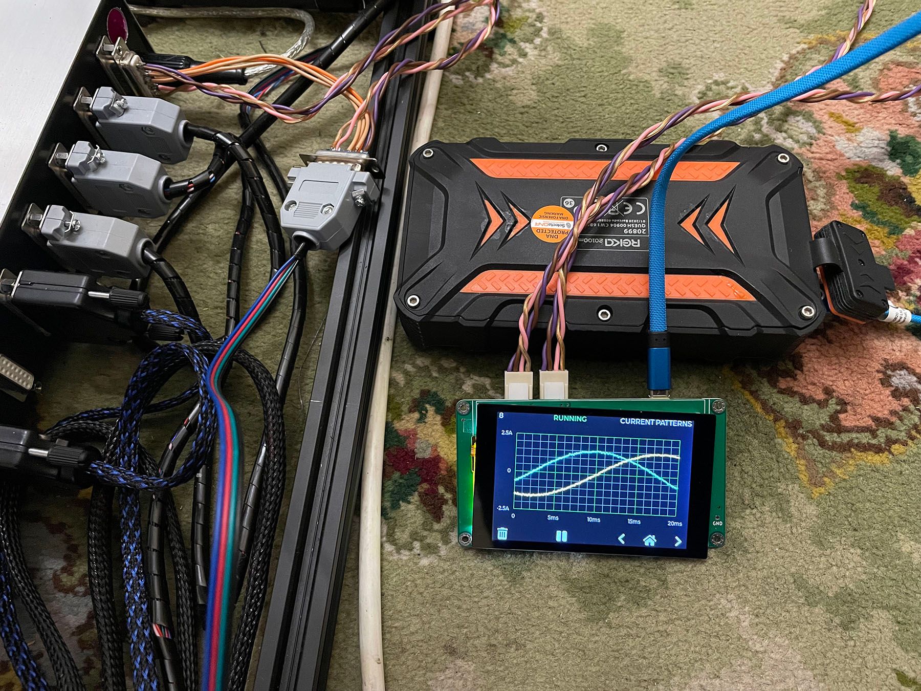
The Mouser TMCS1101A4BQDT ICs seem to work perfectly!
I've made a harness to connect in to the axis motor sockets on the control box, which is fine for those (but the extruders are run from individual toolboards).
[I have printed an enclosure, but then discovered I don't have any thin double-sided tape to attach the display... I'll get some later on].


-
@rjenkinsgb, very nice build!
A couple of notes:
- Theoretically the analyzer needs only 4 wires to measure the currents of the two coils. You can build a harness that has only 4 wires with Y splitting on both ends.
- For double sided tape for the TFT, I had good experience with this kind of thermal tapes. They hold well and designed to be isolating. https://www.amazon.com/gp/product/B072JJD2ND . I also use them between the Pico and the PCB for extra isolation.
- You mention residual current (0.04A in the picture). I presume that you set the zero in the Settings screen.
-
A question for the people that uses various current sensors, how do tell the firmware what is the mv/A sensitivity of the sensor you use?
I don't think that this kind of equipment needs to be supper accurate in the current measurement but it's nice to keep it reasonably close, e.g. +/-5%.