Setting up Duet2 Wifi for TronXY X5SA
-
@pyper I'm currently fitting a Duet 2 WiFi to a TronXY X5S that was donated to me, which is the older version of the X5SA. I recommend using the RepRapFirmware configuration tool to create a set of config files: https://configtool.reprapfirmware.org/.
For converting a printer from alternative board/firmware, and what information to capture to put in the configuration tool, see https://duet3d.dozuki.com/Wiki/Going_from_Marlin_on_Arduino_to_RepRapFirmware_on_DuetI don't know exactly what the differences are between the two, but I'm happy to share my configuration with you, if it helps. The main differences from stock with mine are:
- Fitted Duet 2 WiFi, running RRF 3.3 RC2
- Straightened belt paths, fitted printed idlers to bearings
- Fitted a BLTouch, instead of using a Z endstop, on custom mount with X endstop
- Each Z motor is on it's own stepper driver (2 and 3), rather than both going to one driver
- Extruder is on driver 4
- Bed origin (X0 Y0) is in the centre
- Printed fan shroud, as the old one was blowing too much air on the heater block; it couldn't get to 200C on 12V if the tool fan was on too! https://www.thingiverse.com/thing:3419531
- Rebuilt hot end with insulation around heater block (Kapton tape)
- Resoldered heatbed so it heats all of it, rather than half, though it's now 1.2ohms rather than 0.6ohms (not tuned it yet, ignore M307 settings for heatbed and hotend)
- In the future I may change 12V PSU for 2x 24V PSU, one dedicated for the bed, controlled by SSR (or swap to spare Duet 3 MB6HC I have).
I haven't got to printing with it yet, so will probably refine some of these settings over time. Let me know if there's any other files you want to see.
Current config.g:
; Configuration file for Duet WiFi (firmware version 3)
; executed by the firmware on start-up
;
; generated by RepRapFirmware Configuration Tool v2.1.6 on Tue Jan 14 2020 12:35:54 GMT+0000 (Greenwich Mean Time)

; General preferences
G90                                                ; send absolute coordinates...
M83                                                ; ...but relative extruder moves
M550 P"TronXY X5S"                                  ; set printer name

M669 K1                                            ; CoreXY kinematics

; Network
M552 S1                                            ; enable network
M586 P0 S1                                         ; enable HTTP
M586 P1 S0                                         ; disable FTP
M586 P2 S0                                         ; disable Telnet

; Dual Z
M584 X0 Y1 Z2:3 E4                                 ; Set drive mapping - 2 Z right, 3 Z left

; Drives
M569 P0 S1                                         ; physical drive 0 goes forwards
M569 P1 S1                                         ; physical drive 1 goes backwards
M569 P2 S0                                         ; physical drive 2 goes forwards
M569 P3 S0                                         ; physical drive 3 goes forwards
M569 P4 S0                                         ; physical drive 4 goes backwards
M350 X16 Y16 Z16 E16 I1                            ; configure microstepping with interpolation
M92 X80.00 Y80.00 Z400.00 E94                      ; set steps per mm
M566 X600.00 Y600.00 Z12.00 E300.00                ; set maximum instantaneous speed changes (mm/min)
M203 X18000.00 Y18000.00 Z600.00 E3600.00            ; set maximum speeds (mm/min)
M201 X1500.00 Y1500.00 Z20.00 E600.00                ; set accelerations (mm/s^2)
M906 X1200 Y1200 Z1000 E1000 I30                    ; set motor currents (mA) and motor idle factor in per cent
M84 S30                                            ; Set idle timeout

; Axis Limits
M208 X-165 Y-165 Z0 S1                         ; set axis minima
M208 X165 Y165 Z400 S0                         ; set axis maxima

; Endstops
M574 X1 S1 P"xstop"                                ; configure active-high endstop for high end on X via pin xstop
M574 Y1 S1 P"ystop"                                ; configure active-high endstop for low end on Y via pin ystop
M574 Z0                                            ; configure Z-probe endstop for low end on Z

; Z-Probe
M950 S0 C"exp.heater3"                         ; create servo pin 0 for BLTouch
M558 P9 C"^zprobe.in" H5 F120 T6000            ; set Z probe type to bltouch and the dive height + speeds
M558 A10 S0.003 B0 R0.2                        ; BLTouch extra settings from Phaedrux
G31 P500 X-30 Y0 Z2.5                            ; set Z probe trigger value, offset and trigger height
M557 X-155:130 Y-155:155 P5                   ; define mesh grid

; Heaters
M308 S0 P"bedtemp" Y"thermistor" T100000 B4092     ; configure sensor 0 as thermistor on pin bedtemp
M950 H0 C"bedheat" T0                              ; create bed heater output on bedheat and map it to sensor 0
M140 H0
M143 H0 S120                                       ; set temperature limit for heater 0 to 120C
M307 H0 A215.5 C661.6 D5.8 S1.00 V11.6 B1          ; enable bang-bang mode for the bed heater and set PWM limit
M308 S1 P"e0temp" Y"thermistor" T100000 B4092      ; configure sensor 1 as thermistor on pin e0temp
M950 H1 C"e0heat" T1                               ; create nozzle heater output on e0heat and map it to sensor 1
M143 H1 S280                                       ; set temperature limit for heater 1 to 280C
M307 H1 B0 R2.215 C155.7:139.8 D7.06 S1.00 V12.2   ; New PID algorithm

; Fans
M950 F0 C"fan0" Q500                           ; create fan 0 on pin fan0 and set its frequency
M106 P0 S0 H-1                                 ; set fan 0 value. Thermostatic control is turned off
M950 F1 C"fan1" Q500                           ; create fan 1 on pin fan1 and set its frequency
M106 P1 S1 H1 T45                              ; set fan 1 value. Thermostatic control is turned on

; Tools
M563 P0 S"T0" D0 H1 F0                             ; define tool 0
G10 P0 X0 Y0 Z0                                    ; set tool 0 axis offsets
G10 P0 R0 S0                                       ; set initial tool 0 active and standby temperatures to 0C

; Custom settings

; Miscellaneous
;M501                                               ; load saved parameters from non-volatile memory
M911 S10 R11 P"M913 X0 Y0 G91 M83 G1 Z3 E-5 F1000" ; set voltage thresholds and actions to run on power loss
T0                                                 ; select first tool
Homeall.g
; homeall.g
; called to home all axes
;
; generated by RepRapFirmware Configuration Tool v3.2.3 on Thu Apr 29 2021 21:58:25 GMT+0100 (British Summer Time)
G91                     ; relative positioning
G1 H2 Z5 F6000          ; lift Z relative to current position
G1 H1 X-335 Y-335 F6000 ; move quickly to X or Y endstop and stop there (first pass)
G1 H1 X-335             ; home X axis
G1 H1 Y-335             ; home Y axis
G1 X5 Y5 F6000          ; go back a few mm
G1 H1 X-335 F360        ; move slowly to X axis endstop once more (second pass)
G1 H1 Y-335             ; then move slowly to Y axis endstop
G90                     ; absolute positioning
G1 X0 Y0 F6000    ; go to first bed probe point and home Z
G30                     ; home Z by probing the bed
Ian
-
@droftarts
Ian,
Thanks so much! That is a good start.
From the 'going from marlin to reprap' page, I don't know the mechanical details of my motors (resolution, microstepping, etc). Is that something I can find in my current marlin setup? Or should I email TronXY support? Or forge ahead and not worry as much about it (I am probably worrying too much haha) -
@pyper You can try and get the settings off your current controller by sending M503, though this won't show the motor current settings as those are set manually with a trimpot. You could measure the reference voltage between the trimpot on each driver and GND, if you really want to know how TronXY set them! For other settings, there seems to be a Marlin config example for the X5SA here: https://github.com/MarlinFirmware/Configurations/tree/import-2.0.x/config/examples/Tronxy/X5SA
Otherwise, don't worry too much; you're unlikely to melt/burn anything too badly. Except...
The one area I would advise caution is around the heatbed. I don't know if this is better on the X5SA than the X5S, but if you can measure the resistance of the bed you'll know what you can do to improve it/make it safer. The heatbed is an enlarged version of this one: https://reprap.org/wiki/PCB_Heatbed#MK3_ALU-Heatbed_Dual_Power
It can be switched between 12V and 24V power by the way the way the wires are soldered to it, but it seems the resistance of early ones were very variable. The heating element is one long wire, but has a centre connection, which means it can be wired as if it was two big resistors, in series or in parallel, or just half of it.Mine was 0.6 ohms, and only half of it was wired! 0.6 ohms means 20A at 12V, giving 240W. 20A is generally too much for most MOSFETs, terminals and fuses (if fitted) on 3D printer boards (the Duet 2 WiFi's are rated at 15A). Anything above 0.8 ohms is okay for 12V, drawing 15A and giving 180W. If you want to upgrade to a 24V PSU (usually a separate PSU just for the bed, controlled by a SSR) bed resistance needs to be around 1.8 ohms (2 ohms at 24V is 12A for 288W). The heatbed on mine allows for switching the voltage, but you have to solder the wires to different pads, which is pretty exciting, as there's a huge lump of aluminium which acts as a heatsink. I did it by putting the heatbed on the family cooker hob with a thermocouple showing the temperature, got it up to 200C, then used a 50W soldering iron with the biggest tip I had to solder the wires on. My heatbed now has a resistance of 1.2 ohms, which means it takes 15 minutes to hit 60C with 12V (10A and 120W). I plan to fit a 24V PSU for the heatbed, but because 24V at 1.2 ohms would draw 20A and give 480W (it would heat up REALLY fast), I'll need to find one that I can drop the voltage down to around 18V (15A, 270W).
Apart from that, it's well worth reading through @Phaedrux's Ender 3 guide as a template for changing the electronics on any printer to a Duet: https://duet3d.dozuki.com/Guide/Ender+3+Pro+and+Duet+Maestro+Guide+Part+1:+Wiring/37
For the stepper motors, see if any of them have a sticker on them with the model number that you can look up. My X, Y and extruder motors are 1.7A, 40mm long, NEMA 17, SL42STH40-6184A-23. No marking on Z motors, but they got noisy if I turned up the motor current, so left them on 1A. However, it doesn't matter that much. Most likely they are 1.8° (200 step per revolution) motors, because 0.9° motors are more expensive and TronXY are cheap! If they are 40mm to 48mm long, they're probably 1.7A. Set current to 80% of that (ie 1.4A, though I set mine to 1.2A, which is plenty), and check if they get hot.
Microstepping can be whatever you want. Start with x16 with interpolation.
Steps per mm can be worked out from the above, and knowing how many teeth are on the pulley; mine have 20 teeth, with 2mm tooth pitch belt. I would imagine yours is the same. Formula:
xy_steps_per_mm = (motor_steps_per_rev ∗ driver_microstep) / (belt_pitch_mm ∗ pulley_number_of_teeth)
So xy_steps_per_mm = (200 * 16 ) / (2 * 20) = 80For Z, I'm pretty sure you will also have TR8*8 rod, which is 4 starts, giving a 2mm lead, but 8mm pitch (movement per rotation).
Z_steps_per_mm = (motor_steps_per_rev * driver_microstep) / thread_pitch
Z_steps_per_mm = (200 * 16) / 8 = 400For the extruder, follow @Phaedrux excellent calibration guide, though you can use my figure of 94 (which was a quick calibration) for a ballpark, or use the number from the Marlin configs of 92 (I don't think TronXY have changed the extruder): https://duet3d.dozuki.com/Guide/Ender+3+Pro+and+Duet+Maestro+Guide+Part+4:+Calibration/40#s165
And, indeed, the Marlin config examples give the same numbers for X5S and X5SA:
* X, Y, Z, E0 [, E1[, E2...]] */ #define DEFAULT_AXIS_STEPS_PER_UNIT { 80, 80, 400, 92.6 }Ian
-
@droftarts said in Setting up Duet2 Wifi for TronXY X5SA:
got it up to 200C,
Really really like your detailed explanation
 I also tinker with the idea maybe next year to shoot a cheap ol tronxy on the bay and convert it to duet (maybe 3 by then...)...
BUT while reading very amused your explanation I had to stop at the heatplate-section, BECAUSE most "cheap" heatplates delaminate/detoriate/de... if they get hotter then 150°C (release toxic gases etc. pp.). Next time it is maybe better to stop there (as long as you are not sure that you have something build to higher heat standards) and do the rest by buying a soldering-iron with more Watt like 80Watt you can get reasonably priced... If you watch the video of e3d explaining how difficult it was for them to make their "high-heat" heatplate that got me at least me settled

Cheers!
-
@droftarts
Thanks SO much.
I do have the exact same motors for X,Y, and extruders: SL42STH40-1684A-23. I will use your settings for the setup.My Z motors DO have a label with number: SL42STH60-1684A. Probably the same as yours.
I checked the oms of my heatbed: 1.7
Hopefully no visits from the fire department any time soon..!I will check the links you mention, again thank you so much
-
@pyper Did your TronXY come with 12V or 24V? 1.7 ohms would take forever to heat up on 12V, and probably wouldn't even get to 60C. It would be good on 24V, but may be pretty close to the limit for the PSU, as most 24V PSUs are 15A, and 1.7 ohms pulls 14.1A and gives 338.8W. That doesn't give much headroom for the hot end to heat up or motors to turn!
Ian
-
@lbi Yeah, I was a bit leery of doing the soldering this way, and by no means recommend or endorse it as a way to solder a heated bed.
But I thought the worst that could happen would be the heating element delaminated, then I could rip it off and fit a nice Keenovo (or similar) silicone bed heater! However, I can't see any evidence of delamination or deterioration, resistance is still fine. I also figured that I'd have to put a lot of heat into the local area with a bigger soldering iron (at, say, 400C+) and risk delaminating the very pads you're trying to solder to. I felt by heating the whole thing there would be less thermal shock. It also has pads for surface mount components (not fitted), so maybe if they're doing those in an oven, the bed should be able to go to 225C for a short period of time.
I'd be really interested to see the E3D video, which I can't find, if you can share a link.
Ian
-
@droftarts
It is a big 24V power supply..
But I have a big build volume, so heating the bed still takes forever though haha
I was trying to get some whambam PEX sheets to stick and they said heat the bed to like 80 and it took FOREVER.. -
yeah title is a bit misleading and you gonna have to watch quite a bit into it, but after a few minutes from start it also tackles their high-temp-heatplate:
https://www.youtube.com/watch?v=HK57OH-dpPk
Best regards
-
@droftarts said in Setting up Duet2 Wifi for TronXY X5SA:
Each Z motor is on it's own stepper driver (2 and 3), rather than both going to one driver
Why did you hook it up this way instead of the synced/dual z motor in series option? Just wondering.
-
@pyper said in Setting up Duet2 Wifi for TronXY X5SA:
@droftarts said in Setting up Duet2 Wifi for TronXY X5SA:
Each Z motor is on it's own stepper driver (2 and 3), rather than both going to one driver
Why did you hook it up this way instead of the synced/dual z motor in series option? Just wondering.
Just because the two motors can be wired together, it doesn't mean they can't get out of sync, unless they are physically connected (perhaps with a belt between the two); if you push down on one side of the bed, it is quite easy to make the leadscrew on that side of the bed turn, and the bed will be out of level.
As I had a spare driver output, and as I'm using a Z probe, I can run a macro to level the bed automatically. It gets even better when you have three leadscrews supporting the bed; the whole bed plane can be levelled automatically, not just left/right levelled.
Ian
-
That makes sense.
Mine came with a z-screw sync belt which works pretty well. -
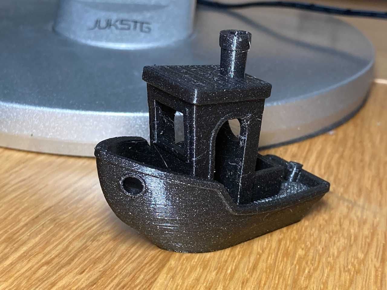
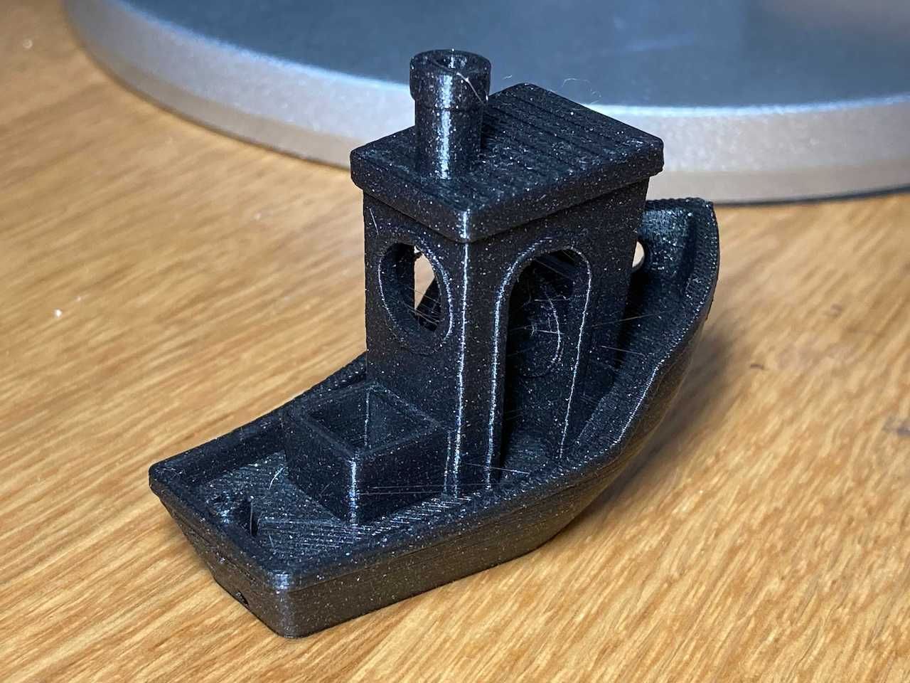
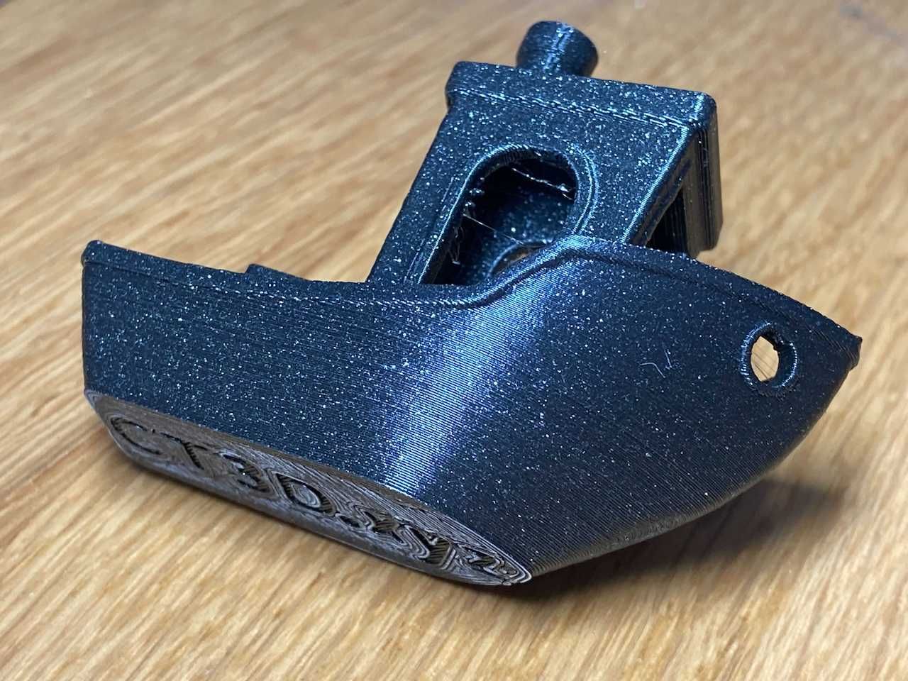
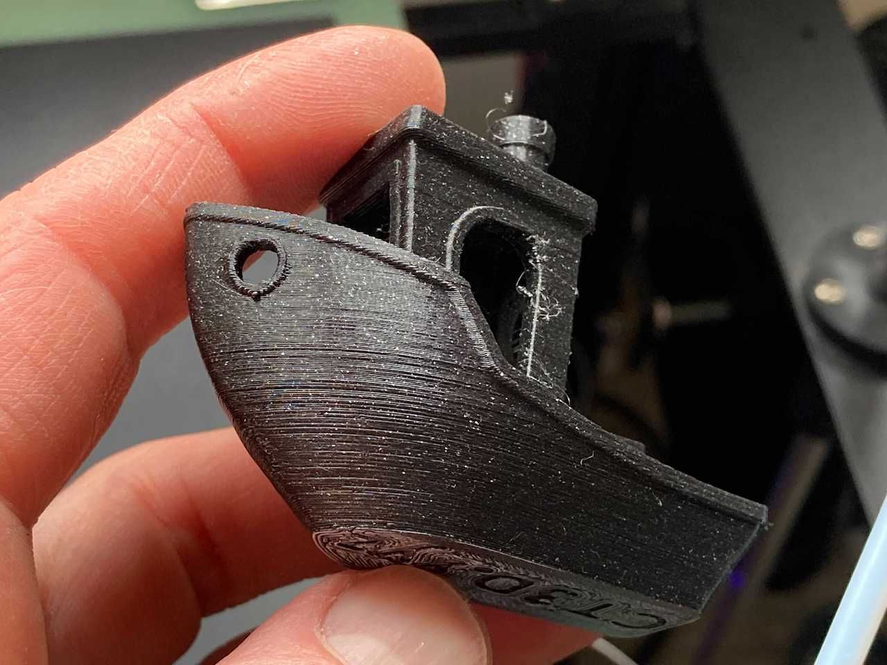
My TronXY X5S managed it's first print the other day. Not perfect, but certainly not bad. Frame wobbles a bit, so not printing too fast (50mm/s printing, 100mm/s travel). Stiffening up the frame with some corner brackets would definitely help. Tuning retraction (currently 3.3mm) and pressure advance (none used atm, and it's got a 850mm long Bowden tube) would also help. I may investigate direct drive extruder replacements. The bed is a bit warped at 60C (and it's only mounted on 3 points), so may have to change the supplied fibreglass (I think) surface for something more substantial. I also had to change the heater block for an E3D V6 block, as the original thermistor died and I only had E3D thermistors to replace it. It fit perfectly, with the added advantage of a silicone heater sock. Time to tidy up the wiring!
Next on the list is to have a separate 24V PSU for the heated bed, as it takes 15 minutes to get to 60C on 12V.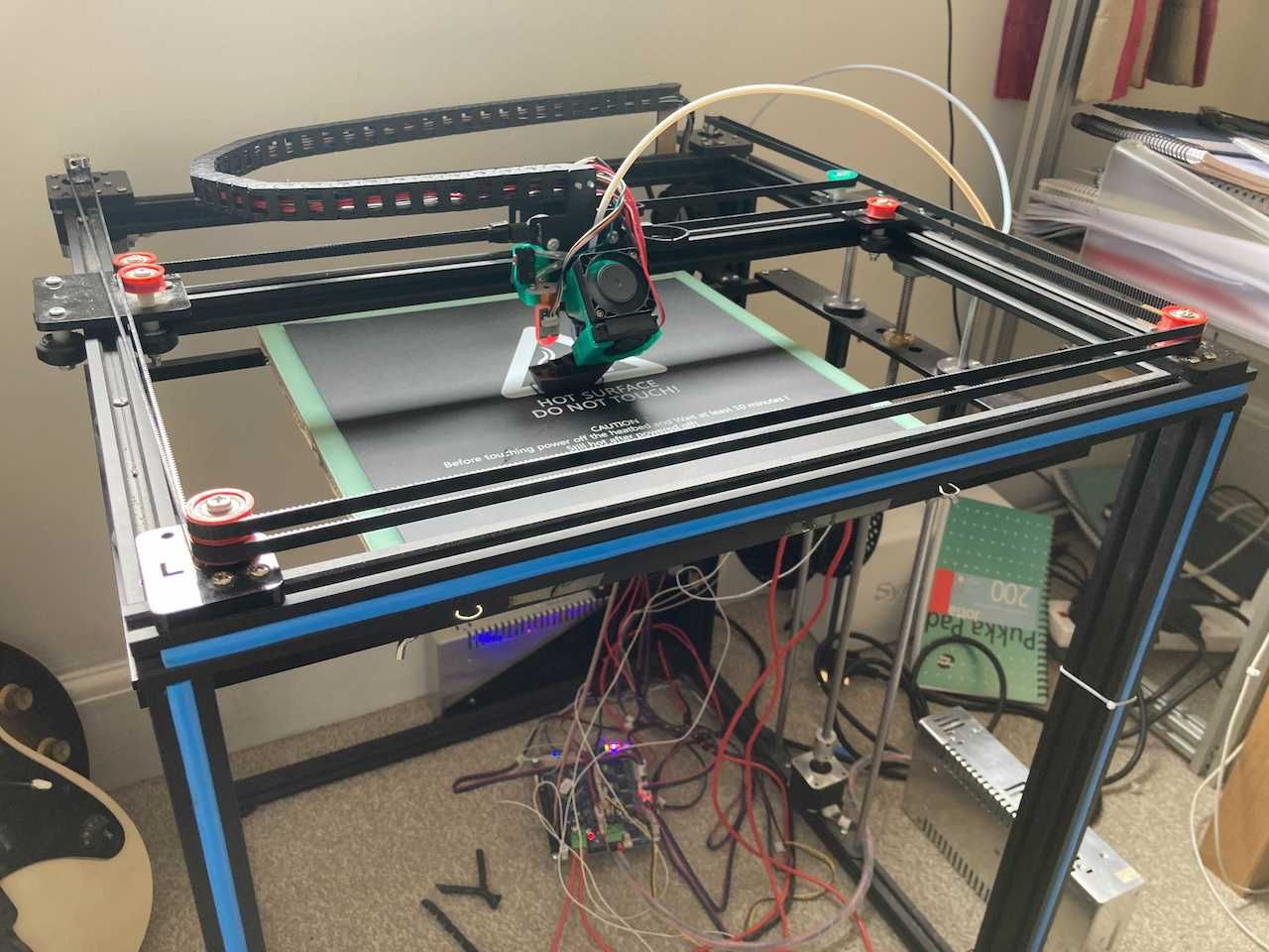
Ian