Mesh Bed Level Issues
-
@droftarts regarding the both z steppers, I also thought in this direction but could not find how others fix it. Seems that I got alot new hints how to tackle the issue. Irrespective the other Tipps I think a proper way to sync the motors is anyhow a good idea
-
IF you have a free driver you can put each Z motor on it's own and then control them independently to do tilt correction.
https://duet3d.dozuki.com/Wiki/Bed_levelling_using_multiple_independent_Z_motors
-
@phaedrux There's an echo in here!
Ian
-
@megaloduet If the bed is not adjustable, and you're happy that it's square to the frame, then most likely the X axis is tilted. As the only thing keeping it up is the Z motors, so probably one of them has slipped. I've just noticed you've got linear rails on all axes; these REALLY don't like being anything other than perfectly perpendicular to each other, and will bind if they are not.
Check the couplers are tight, too. As the couplers are the compressible springy kind, the best thing to do is to put a ball bearing in the middle of it, resting on the top of the motor shaft, with the leadscrew resting on top of the ball bearing. This stops the coupler compressing under load, but still lets it do what it's designed to do, which is to account for any movement in the leadscrew, eg if it's bowed.
Ian
-
Sounds like you have some good suggestions to look into already.
I totally agree that if your Z axis is binding, it will not be able to track with the tiny mesh compensations. You could physically test this by setting up an indicator between the carriage and bed, then requesting tiny Z moves up and down, to see if the actual motion is reliable.
I leveled our i3 MK3 bed mechanically at work by using shim stock between the bed and the spacers. Works beautifully. But, I agree, check the X axis first, might save you a bunch of work.
Also, double check that your probe offset values are truly correct. It isn't hard to get them inverted. You can command your print head to the 4 corners of a bounding box, and mark them with a marker or tape. Then define that mesh boundary and probe, looking for good probe alignment to the box.
-
@droftarts just ordered 8mm steel balls, to rule this out as well, seems like a good tipp anyhow.
Did manually level the X axis, this slightly improved the result, but still same artifacts with less magnitude. I noticed a Z motor was slightly tilted. Didnt had time to decouple the Z Stepper motors and to make them indepedent, will update soon. However do you have any tipp to test for binding? If I move the z motors by hand it seems to run smooth.
Will collect the results of today and will upload it tomorrow, for further details on improvement.
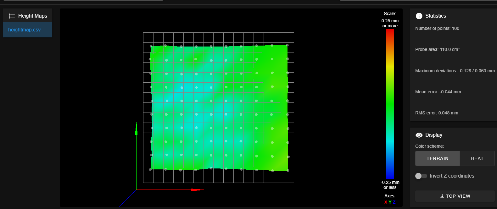
This is what the heighmap looks now:

-
"I totally agree that if your Z axis is binding, it will not be able to track with the tiny mesh compensations. You could physically test this by setting up an indicator between the carriage and bed, then requesting tiny Z moves up and down, to see if the actual motion is reliable."
You mean like measuring it with a feeler gauge, moving z axis up down left right and back to the spot and see if its still exactly like before (the same distance measured with a feeler gauge?"Also, double check that your probe offset values are truly correct. It isn't hard to get them inverted."
I will also double check but I think I already did that as well. -
@megaloduet said in Mesh Bed Level Issues:
"I totally agree that if your Z axis is binding, it will not be able to track with the tiny mesh compensations. You could physically test this by setting up an indicator between the carriage and bed, then requesting tiny Z moves up and down, to see if the actual motion is reliable."
You mean like measuring it with a feeler gauge, moving z axis up down left right and back to the spot and see if its still exactly like before (the same distance measured with a feeler gauge?"Also, double check that your probe offset values are truly correct. It isn't hard to get them inverted."
I will also double check but I think I already did that as well.It looks like you have mechanically made more than a slight improvement. Your RMS error is reduced about 70%.
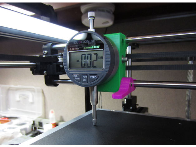
I was suggesting to mount a dial indicator to your print head, like this:

Then, command tiny Z moves up and down to simulate mesh leveling corrections. See if the measured movement matches the commanded distances.
-
@ccs86 ordered the device will come in latest in the weekend. Then we know more and have numbers. Thank you mate