* Circle Jerks *
-
I'm facing (two current) issues and don't know if they are related. In an effort to solve the issue of my printer not printing arcs/curves properly:
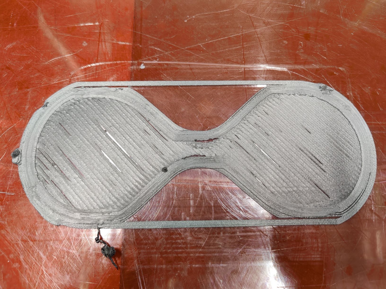
That should be a figure eight with arcs connecting the two 100mm outside circles
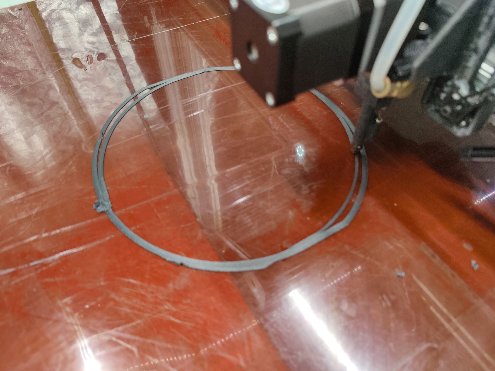
There's some issue with the X axis that seems to not complete the full arc.
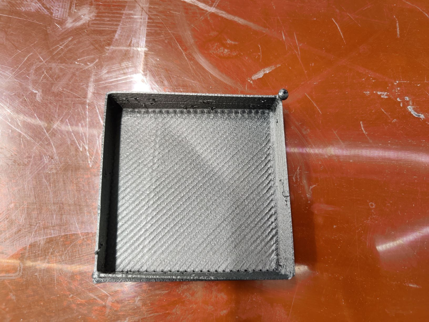
Will print squares without a problem:
So I thought I'd see if the firmware needed a refresh because going through the X drive system (helical rack and pinion and shielded cable to the Duet 3 board) I couldn't see an issue <apart from ever finer tuning the step calibration obviously>.
Now on another printer, running the same FW , the hourglass prints fine, curves in all the right places, same slicer, practically the same settings apart from build volume.
I've tried changing; instantaneous speed, steps/mm in conjunction with microstepping, my t shirt, nada. Doesn't seem to affect the shape or placement of the dents.
My next thought was the wiring between the X stepper and the expansion board but moving a curved part around the bed produces similar errors.
Any ideas why my circles might be dented and jerky would be very helpful.
Posting config in case:
; Configuration file for Duet 3 (firmware version 3) ; executed by the firmware on start-up ; ; generated by RepRapFirmware Configuration Tool v3.1.7 on Tue Nov 17 2020 15:11:50 GMT+0000 (Greenwich Mean Time) ; General preferences G90 ; send absolute coordinates... M83 ; ...but relative extruder moves M550 P"Usain" ; set printer name ; Drives M569 P0.0 S1 ; physical drive 0.0 goes (right Y motor) forwards Y1 M569 P1.2 S1 ; physical drive 1.2 goes (left Y motor) forwards Y2 M569 P0.2 S1 ; physical drive 0.3 (right) goes forwards Z1 M569 P0.3 S0 ; physical drive 0.2 (left) goes forwards Z1 M569 P0.4 S0 ; physical drive 0.2 goes forwards U M569 P1.0 S0 ; physical drive 1.0 goes forwards X1 M569 P1.1 S0 ; physical drive 1.1 goes forwards E1 ;M569 P1.2 S1 ; physical drive 1.1 goes forwards E1 M584 X1.0 Y0.0:1.2 Z0.2:0.3 E1.1:0.4 ; set drive mapping ;M671 X-60:790 Y0:0 S0.5 ; leadscrews at left (connected to 0.2) and right (connected to 0.3) of X axis M350 X8 Y8 Z16 E16 I1 ; configure microstepping with interpolation M92 X19.14495 Y20.3065 Z1711.63 E500 ; set steps per mm X38.2899 Y40.613 M566 X1800.00 Y1850.00 Z80.00 E520.00 P1 ; set maximum instantaneous speed changes (mm/min) M203 X95000.00 Y48000.00 Z580.00 E1800.00 ; set maximum speeds (mm/min) M201 X1550.00 Y1400.00 Z20.00 E150.00 ; set accelerations (mm/s^2) M906 X2300 Y2450 Z2200 E1000 I30 ; set motor currents (mA) and motor idle factor in per cent M84 S30 ; Set idle timeout ; Axis Limits M208 X0 Y0 Z0 S1 ; set axis minima M208 X720 Y2800 Z800 S0 ; set axis maxima M564 H1 S1 ; Endstops M574 X1 S1 P"1.io0.in" ; configure active-high endstop for low end on X via pin 1.io0.in M574 Y1 S1 P"!io0.in" ; configure active-high endstop for low end on Y via pin io0.in M574 Z1 S2 ;P"1.io1.in" M574 Z1 S1 P"!io1.in" ; configure Z active-high endstop for low end pin 1.io1.in ; Filament Sensor ;M591 D0 P5 C"1.io3.in" R40:120 S0 ; Duet3D laser sensor for extruder drive 0, connected to endstop input 3 (E0), tolerance 40 to 120%, 3mm comparison length, disabled ; Z-Probe ;M558 P8 C"1.io2.in" R0.4 I1 S0.1 A5 H8 F320 T6000 ; set Z probe type to modulated and the dive height + speeds ;G31 P500 X30 Y5 Z0.275 ; set Z probe trigger value, offset and trigger height ;M557 X15:690 Y15:1800 S55 ; define mesh grid ; Heaters M308 S0 P"temp0" Y"pt1000" A"bed Heat1" ; configure sensor 0 as thermistor on pin temp0 M950 H0 C"out1" T0 ; create bed heater output on out0 and map it to sensor 0 M307 H0 A22.7 C156.4 D4.0 S1.0 ; disable bang-bang mode for the bed heater and set PWM limit M140 P0 H0 ; map heated bed 0 to heater 0 M143 H0 S90 ; set temperature limit for heater 0 to 90C M308 S1 P"temp1" Y"pt1000" A"bed Heat2" ; configure sensor 1 as pt1000 on pin temp1 (T100000 B4138) M950 H1 C"out2" T1 ; create nozzle heater output on out1 and map it to sensor 1 M307 H1 A22.7 C156.4 D4.0 S1.0 ; disable bang-bang mode for the bed heater and set PWM limit M140 P1 H1 ; map heated bed 1 to heater 1 M308 S2 P"temp2" Y"thermistor" A"bed Heat3" T100000 B4138 ; configure sensor 2 as thermistor on pin temp2 M950 H2 C"out3" T2 ; create nozzle heater output on out2 and map it to sensor 2 M307 H2 A32.7 C156.4 D4.0 S1.0 ; disable bang-bang mode for the bed heater and set PWM limit M140 P2 H2 ; map heated bed 1 to heater 1 M308 S3 P"1.temp0" Y"pt1000" A"Prime_Heater_100W" ; configure sensor 3 as a pt1000 on pin 1.temp0 (T100000 B4138) M950 H3 C"1.out0" T3 ; create nozzle heater output on 1.out0 and map it to sensor 3 M307 H3 A590 C962.6 D5.5 S0.5 V24.3 B0 ; disable bang-bang mode for heater and set PWM limit M308 S4 P"1.temp1" Y"pt1000" A"Prime_Heater_60W" ; configure sensor 4 as thermistor on pin 1.temp1 M950 H4 C"1.out1" T4 ; create nozzle heater output on 1.out1 and map it to sensor 4 M307 H3 A590 C962.6 D5.5 S0.5 V24.3 B0 ; disable bang-bang mode for heater and set PWM limit ; Fans M950 F0 C"1.out6" Q500 ; create fan 0 on pin 1.out6 and set its frequency M106 P0 S0.55 H3 C"Plastic" ; set fan 0 value. Thermostatic control is turned on M950 F1 C"1.out7" Q500 ; create fan 1 on pin 1.out7 and set its frequency M106 P1 S1 H-1 C"part_cooling_2" ; set fan 1 value. Thermostatic control is turned on M950 F2 C"1.out8" Q500 ; create fan 2 on pin 1.out8 and set its frequency M106 P2 S1 H-1 C"part_cooling" ; set fan 1 value. Thermostatic control is turned off ; Tools M563 P0 S"Prime_Extruder_100W" D0 H3 F1:2 ; define tool 0 G10 P0 X0 Y0 Z0 ; set tool 0 axis offsets G10 P0 R0 S0 ; set initial tool 0 active and standby temperatures to 0C M563 P1 S"Prime_Extruder_60W" D0 H4 F1:2 ; define tool 1 G10 P1 X0 Y0 Z0 ; set tool 0 axis offsets G10 P1 R0 S0 ; set initial tool 0 active and standby temperatures to 0C ;M567 P4 E0.5:0.50 ; set mixing ratio for tool 0 ;M563 P1 S"Filament Feed" D1 H3 ;G10 P0 X0 Y0 Z0 ; set tool 0 axis offsets ;G10 P0 R0 S0 ;M563 P2 S"Prime_Support_Extruder" D2 H5 F3 ; define tool 2 ;G10 P2 X0 Y0 Z0 ; set tool 2 axis offsets ;G10 P2 R0 S0 ; set initial tool 2 active and standby temperatures to 0C ; Custom settings are not defined ; Miscellaneous M911 S10 R11 P"M913 X0 Y0 G91 M83 G1 Z3 E-5 F1000" ; set voltage thresholds and actions to run on power loss -
Seems to be a mechanical issue...
are the axles running smoothly without much resistance? Are all pulleys tighten? -
@madeinta1wan It's almost certainly a mechanical backlash issue. Either something is loose (like a pulley on a motor shaft) and moving back and forth, or something is tight (like a bearing on a shaft) and is resisting moving until the driving force overcomes the inertia. Check through your X axis mechanism.
Ian
-
@madeinta1wan Those position errors are large enough you will be able to see them by moving the head a specific amount and measuring how far it moved.
Try taping something to your printhead like a pencil or a piece of wire so that it almost touches the print bed.
Put a ruler onto your print bed aligned with the Y axis.
Move the head using GCODE a certain amount and see where the pencil or wire goes.
Here's what I would do:
- Move to zero
- Move to 100mm. See where it goes
- Move to 90mm
- Move to 100mm. See if it goes EXACTLY back to 100mm
- Move to 10mm and measure
- Move to 0mm and measure.
- Move to 5mm and measure.
If you don't get exactly the right measurements, let us know what they are and we'll be able to help.
-
Thanks everyone for the rapid response!
I should clarify and specificy-
Both the X axis and Y axis operate on directly driven helical rack and pinion. The Y axis is 3200mm long and the X axis is 1200mm. While the Y axis has two Nema 23 motors driving either side the X axis has a single Nema 23 motor. It's quite evident and at present unlikely that there's no obvious mechanical play in either axis. The holding torque of the motors means that unless you actually bash the gantry, it's not moving.
The other reason that I'm apt to dismiss purely mechanical play as the cause for this is that if I move the test cylinder print to anywhere else on the bed, a meter in Y and 500 mm in X - the same thing happens in exactly the same place. It would seem to me that there was as @droftarts @alankilian @cosmowave say- a backlash or improper position and reposition (although I'm going to try what you say now @alankilian just to be sure), that the circle would deform in different places depending on where it was on the bed, say closer to the axis limit. Rather than this behavior of having the same amount of flattened sides along the X axis anywhere the cyclinder (or figure eight) is placed on the bed.
For reference this is the last print from my printer:
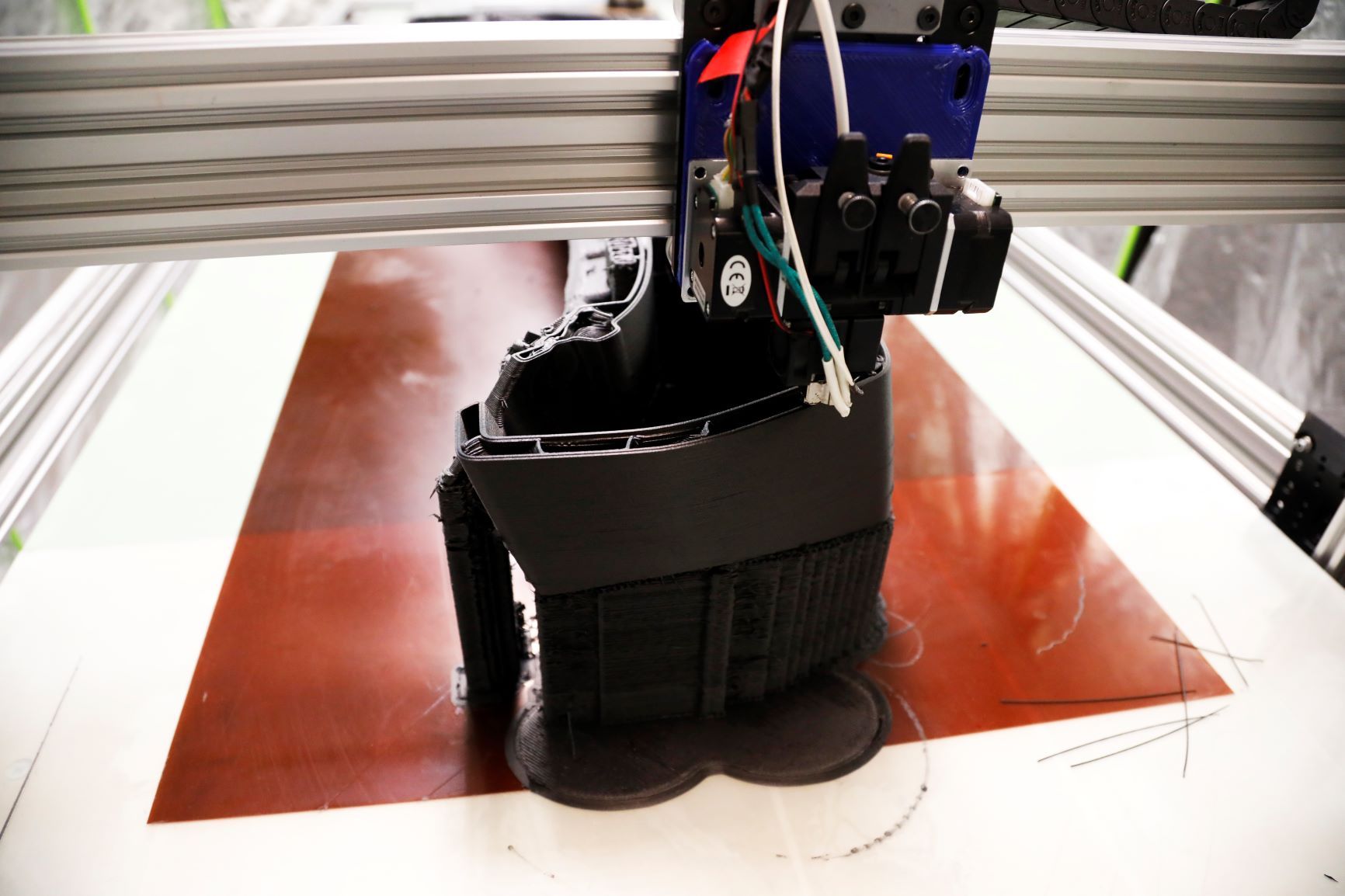
Which is now zooming around the world on this:

Since then it's developed this very silly behaviour, which I'm assuming is my fault but I'm unable to suss out where this particular gremlin is living.
-Nate
-
@madeinta1wan if it’s the case the deformation is uniform across the bed, I’d look at the pinion gear and how well it’s secured on the motor shaft first. Then at the linkage that hold the hot end to the rack, then if there’s any lateral play in the rack.
Ian
-
@madeinta1wan with it being a helical rack and pinion, I'd be especially looking at the pinion gear mounting. It will generate an axial load on the pinion shaft (so you need to consider axial backlash/clearance/play on that shaft as well as the normal backlash in the mesh.
Is that axial load taken by the motor bearings? They're often axial spring loaded so the shaft can expand freely without putting thermal stresses on everything, but that means they can't take axial loads very well -
I think this is probably what I'm seeing @droftarts and @engikeneer , while it doesn't seem to be present as much (or at all) in the Y axis, the X axis recently had a bracket upgrade that included some IGUS linear guides that seemed to be quite tight in the channel they run along.
I swapped out the helical gear from a 28 tooth one to a 44 tooth to see if that made any difference and it looks like the overall torque to move the now more supported bracket looks like I've introduced far more friction than I had before. Which in turn looks like it's either causing the motor to stall or the pinion to slip.
Thanks both for your help.