Air pump too fast at minimum pwm
-
@alankilian said in Air pump too fast at minimum pwm:
Yeah, that's going to give you some strange traces.
It depends on the design of the scope.
I use a battery powered scope and I could connect it as shown and get a pseudo-differential view of the voltage across the motor.
A line powered scope can be designed to allow the same though a true differential probe would be preferred.
How you connect the scope depends mostly on the signal you wish to view.
Frederick
-
@fcwilt True, but the voltage across the motor without a ground reference isn't going to tell you things about the risetime and falltime of the control signal.
That's likely why you see 39 Volts across the motor. It's just inductive kickback.
Maybe you should add a very small value series resistor attached to the VIN side of the motor and measure from VIN to the other side of the resistor. That would get you motor current which is probably what you're looking for.
To get back to your problem, what kind of motor is in the air pump?
It might not even be able to be speed-adjusted much by varying the PWM of it's power supply.Maybe you'd be better off looking into an adjustable blowoff valve to toss some of the air overboard.
I'm thinking as hard as I can about how to get you what you want and I'm not coming up with great ideas, I'm sorry.
-
One other thought is to use a high-current medium-value inductor in series with your pump motor.
I've used those in systems where the motor's armature inductance was too low to get good speed control from a PWM signal.
Something to try anyway.
-
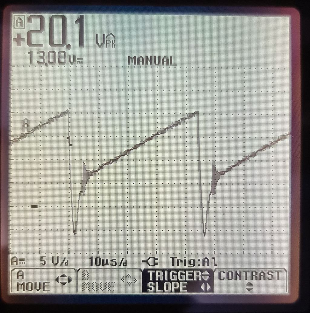
@alankilian You are right, the low side switching has gotten me several times over the years. Below is a trace of the motor running at 1% pwm with the scope gnd connected to actual gnd and the signal probe to the negative terminal of the motor.
For those who requested it, here a link to the pump I got.
-
Hi,
How are you setting the 1%?
The scope image simple doesn't look like 1% to me - unless I'm completely looking at it wrong.
Thanks.
Frederick
-
@fcwilt I am setting the 1% in the DWC machine control dashboard tab
-
I wonder if this is part of the problem.
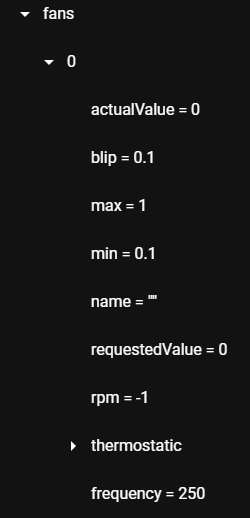
This is a screen shot of the DWC Object Model showing the fan data for a Duet 3 Mini 5 I am testing running firmware 3.2.
Notice the min and max values.
IF they are being enforced this fan cannot be set to 1%.
That might explain why the scope image doesn't look like 1% to me.
I need to do some testing.
Frederick
-
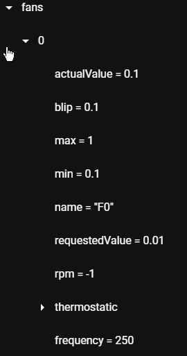
OK I issued M106 P0 S0.01
This is what the object model shows now.
Does this object model reflect what the fan output is actually doing?
I don't know.
But if the object model DOES correctly indicate what the fan output is doing it would explain why 1% is as not slow as you expected.
Frederick
-
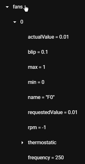
To the M106 command in my config.g file for this fan I added this parameter and value L0.
Then I issued the M106 P0 S0.01.
This is the object model now.
At this point it might help if @dc42 would jump in and clarify default fan settings like min speed when no M106 L parameter is present.
In the meantime add L0 to the appropriate M106 in your config.g file and see it it makes a difference in the behavior of the pump.
-
Hi,
OK I took the time to configure out1 on the Duet 3 Mini as a fan.
M950 F0 C"out1" Q500
M106 P0 S0 H-1 C"F0"
Notice there is no L parameter.
I connected a 1K resistor across the outputs and connected my battery powered scope leads across the resistor.
The scope has the ability to measure the duty cycle of a waveform and I enabled that feature.
I re-booted the board and issued a M106 P0 S0.01 command.
The object model reported that the actual value was 0.1.
The scope reported the duty cycle to be 10%.
I changed the fan setup to this:
M950 F0 C"out1" Q500
M106 P0 S0 H-1 C"F0" L0
I re-booted the board and issued a M106 P0 S0.01 command.
The object model reported that the actual value was 0.01.
The scope reported the duty cycle to be 1%.
So at least with firmware 3.2 on a Duet 3 Mini 5, the default L value for a fan is 0.1.
And that explains why the pump would not go as slow as you wanted.
Add the L parameter using whatever min value is suitable and you should be good to go.
That was fun.
Frederick
-
Is scope ground connected to Duet ground, i.e. VIN- or the GND pin of any of the I/O connectors? I have a feeling that it isn't, which is why the trace is still odd.
-
@dc42 In the last trace I posted the scope ground was connected with a wire straight to the psu negative terminal.
@fcwilt I never knew that there was a default min value, thanks for pointing that out. I have put it at 0 now and that definitely helped. The trace looked quite similar though, ie. as saw tooth.
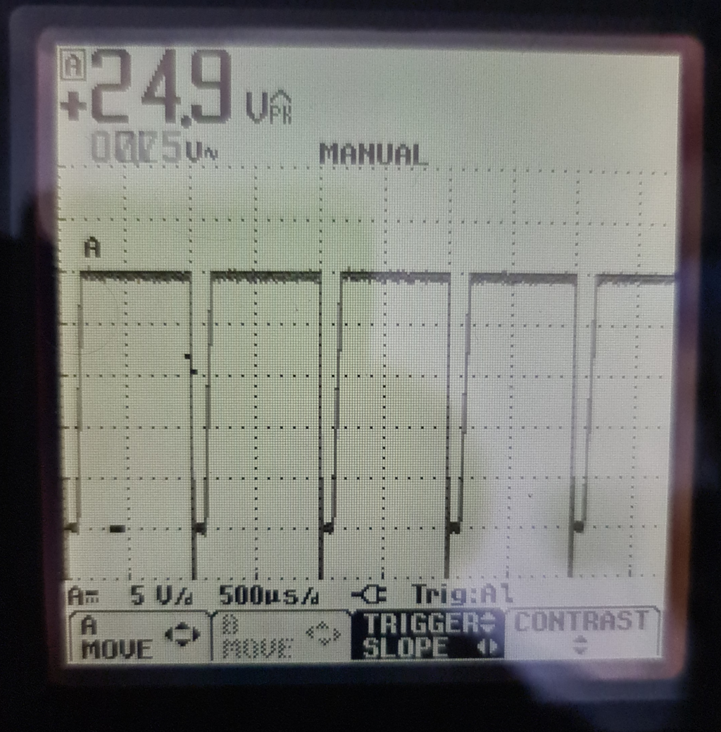
At this point I was ready to call it a day and slap a power resistor in series (which I tried and worked decently well) to drop the voltage. Out of curiosity and recalling that dc pointed out that the 22.5kHz switching frequency was very high, I tested again at 1kHz. (this was at like 4% or something similar). The trace speaks for itself I guess.
I draw two conclusions from this. 1) The previous trace was not a measurement error as the setup did not change, only the frequency of operation. 2) The E1 mosfet on the duet cannot switch fast enough, there are unwanted capacitances or something in that area. At least the conclusion is something does not like higher switching speeds.
EDIT: just to avoid confusion, all the traces I post here are scope gnd to actual gnd and scope signal to the negative terminal of the pump.
-
Here are two more traces:
5% @2kHz
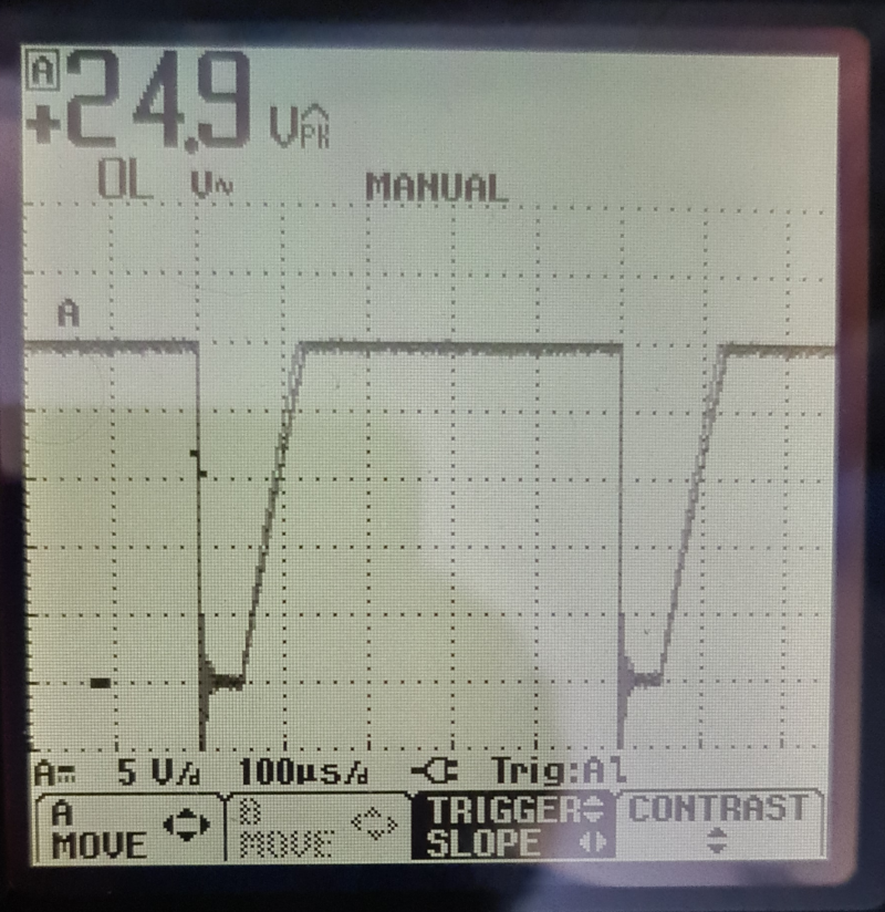
5% @5kHz
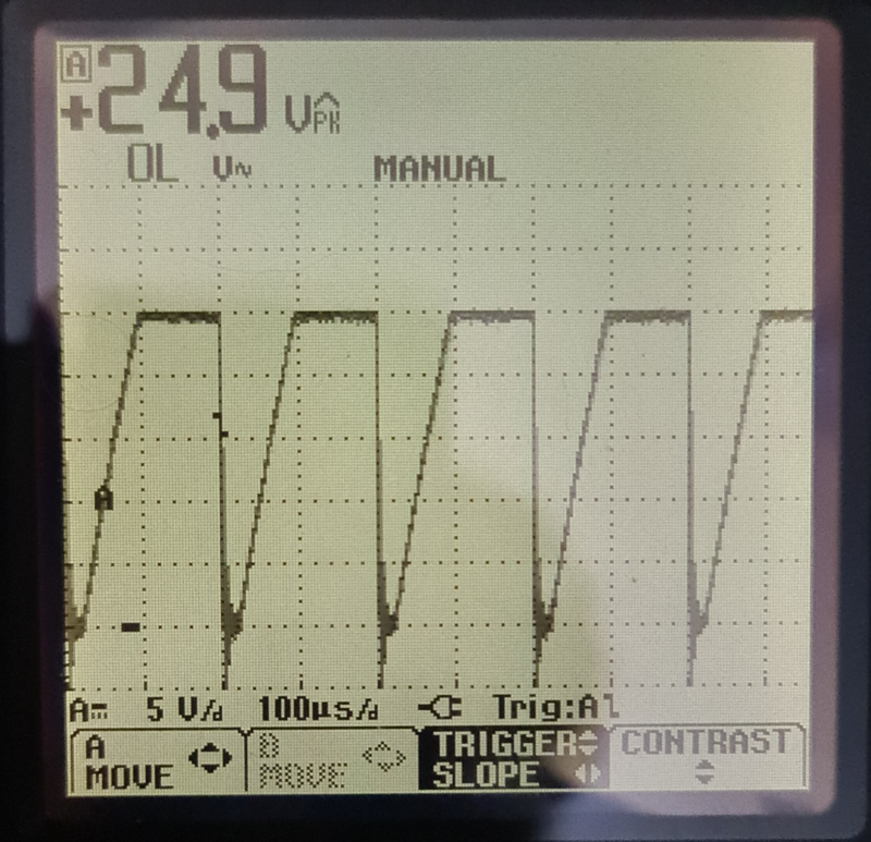
-
@alankilian said in Air pump too fast at minimum pwm:
I think things will look better if you connect the scope ground to ground and scope-signal to E1-.
You'll see a zero-volt signal when the pump is "on" and a woozy-doozy signal probably getting up to 24 Volts when the pump is "off".PERFECT!
I think you've demonstrated that everything is working exactly as it's supposed to even at 22 KHz.
That minimum of 10% was certainly buried in the details. Thanks @fcwilt for finding that.
Now, how do we get your darn motor to slow down more?
Or, can you just make a "leak" in the output hose to let off 50% of the air and then you'll be able to control it enough?
Or can you restrict the output through an orifice to limit the air?
We'll get you there somehow.
Great investigative work.
-
Hi,
Are you sure the L0 parameter took hold?
The image labeled 5% at 2kHz looks like10% - which is the default minimum - what you get with no L parameter.
Frederick
-
@fcwilt said in Air pump too fast at minimum pwm:
Hi,
Are you sure the L0 parameter took hold?
The image labeled 5% at 2kHz looks like10% - which is the default minimum - what you get with no L parameter.
Frederick
You are right in between setting the different frequencies the L parameter got overridden. If I set it again and look at the trace it has a half as long off period than before, as it should be. The rise time the same or similar.
-
-
@fcwilt said in Air pump too fast at minimum pwm:
So can you get the pump running slow enough now?
Frederick
Yes, no, maybe? I think it's slow enough now, it does make some progressively unhappy noises as low percentages as I drop the frequency. For now, I have some things I really need printed so I am going to roll with it @2kHz I think

For sure many thanks for those who contributed.
-
@Nxt-1 said in Air pump too fast at minimum pwm:
Yes, no, maybe? I think it's slow enough now, it does make some progressively unhappy noises as low percentages as I drop the frequency.
If a motor is designed to run on pure DC then PWM DC can make it sound unwell.
There are filter circuits you can add between the board connections and the motor that can smooth out the pulses giving something more like DC.
It might make a suitable improvement.
Frederick
-
@fcwilt said in Air pump too fast at minimum pwm:
PWM DC can make it sound unwell.
Also, 2,000 Hz is a pretty annoying frequency.