Mirror image and homing on x axis
-
Mirror image and homing on x axis
Hi all
Any forum member who can help point me in the right direction, it would be much appreciated.The printer produces components with a mirrored x axis, (y axis is ok).
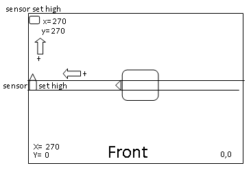
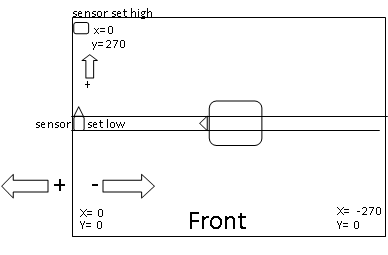
At the moment the 0, 0, position is to front right side, looking from the front of the printer, the front left side is what is required. When I do get it to home and read 0, 0 in the left corner the + and – readings are the wrong way round reading –towards the bed not +.
Motor 1 left side front, motor 2 right side front.
Maximum axis travel set to x270, y270.
At the moment x homing sensor is to the left and is set high, (this in practice should be set to low)
On homing this gives the position x=270 giving a mirror image (0 being required).
If the sensor is set to low side (as it should be) it will home to give x=0, but the bed side to the right then reads 0 to-270 (not the required 0 to 270)

I have tried all combinations in config. g, homex.g and homeall.g without a result.All suggestions will be welcome
Board: Duet Maestro 1.0
Firmware: RepRapFirmware for Duet 2 Maestro 2.05.1 (2020-02-09b1)
Duet Web Control 2.0.4; Configuration file for Duet Maestro (firmware version 2.03)
; executed by the firmware on start-up
;
; generated by RepRapFirmware Configuration Tool v2.1.8 on Sun Feb 23 2020 15:16:31 GMT+0100 (Central European Standard Time); General preferences
G90 ; send absolute coordinates...
;M83 ; ...but relative extruder moves (will give negative retract moves)
M82 ; .. but absolute extruder moves (will give positive retract moves)
M550 P"HyperCube Printer" ; set printer nameM667 S1 ; select CoreXY mode
M918 P1 E4 F2000000 ; configure direct-connect display; Network
M551 P"hypercube" ; set password
M552 P192.168.1.171 S1 ; enable network and set IP address
M553 P255.255.255.0 ; set netmask
M554 P192.168.1.254 ; set gateway
M586 P0 S1 ; enable HTTP
M586 P1 S0 ; disable FTP
M586 P2 S0 ; disable Telnet; Drives
M569 P0 S1 ; physical drive 0 goes forwards
M569 P1 S1 ; physical drive 1 goes forwards
M569 P2 S0 ; physical drive 2 goes backwards
M569 P3 S0 ; physical drive 3 goes backwards
M584 X0 Y1 Z2 E3 ; set drive mapping
M350 X16 Y16 Z16 E16 I1 ; configure microstepping with interpolation
M92 X80 Y80 Z400.00 E415.00 ; set steps per mm
M566 X900.00 Y900.00 Z60.00 E600.00 ; set maximum instantaneous speed changes (mm/min)
M203 X12000.00 Y12000.00 Z120.00 E1200.00 ; set maximum speeds (mm/min)
M201 X800.00 Y800.00 Z20.00 E10000.00 ; set accelerations (mm/s^2)
M906 X900 Y900 Z900 E500 I30 ; set motor currents (mA) and motor idle factor in per cent
M84 S30 ; Set idle timeout; Axis Limits
M208 X0 Y0 Z0 S1 ; set axis minima
M208 X270 Y270 Z270 S0 ; set axis maxima; Endstops
M574 X2 Y2 S1 ; set active high endstops
M574 Z1 S2 ; set endstops controlled by probe; Z-Probe
M558 P9 F100 H5 R0.2 T6000 A5 B1 ; set Z probe type to bltouch and the dive height + speeds
;M558 H30 ;*** Remove this line after delta calibration has been done and new delta parameters have been saved
G31 P500 X30 Y0 Z0.798 ; set Z probe trigger value, offset and trigger height
M557 X60:270 Y30:260 S25 ; define mesh grid; Heaters
M307 H0 B0 S1.00 ; disable bang-bang mode for the bed heater and set PWM limit
M305 P0 T100000 B4138 R2200 ; set thermistor + ADC parameters for heater 0
M143 H0 S80 ; set temperature limit for heater 0 to 80C
M305 P1 T100000 B4138 R2200 ; set thermistor + ADC parameters for heater 1
M143 H1 S240 ; set temperature limit for heater 1 to 240c; Fans
M106 P0 S0 I0 F500 H-1 ; set fan 0 value, PWM signal inversion and frequency. Thermostatic control is turned off
M106 P1 S1 I0 F500 H1 T45 ; set fan 1 value, PWM signal inversion and frequency. Thermostatic control is turned on; Tools
M563 P0 S"E3D V6" D0 H1 F0 ; define tool 0
G10 P0 X0 Y0 Z0 ; set tool 0 axis offsets
G10 P0 R0 S0 ; set initial tool 0 active and standby temperatures to 0C; Custom settings are not defined
; homeall.g
; called to home all axes
;
; generated by RepRapFirmware Configuration Tool v2.1.8 on Sun Feb 23 2020 15:16:31 GMT+0100 (Central European Standard Time)
G91 ; relative positioning
G1 H2 Z5 F3000 ; lift Z relative to current position
G1 H1 X255 Y275 F1800 ; move quickly to X or Y endstop and stop there (first pass)
G1 H1 X255 ; home X axis
G1 H1 Y275 ; home Y axis
G1 X-5 Y-5 F3000 ; go back a few mm
G1 H1 X255 F360 ; move slowly to X axis endstop once more (second pass)
G1 H1 Y275 ; then move slowly to Y axis endstop
G90 ; absolute positioning
G1 X165 Y135 F3000 ; go to first bed probe point and home Z
G30 ; home Z by probing the bed
G29 S1 ; load mesh map from sd card; Uncomment the following lines to lift Z after probing
;G91 ; relative positioning
;G1 Z5 F50 ; lift Z relative to current position
;G90 ; absolute positioning; homex.g
; called to home the X axis
;
; generated by RepRapFirmware Configuration Tool v2.1.8 on Sun Feb 23 2020 15:16:31 GMT+0100 (Central European Standard Time)
G91 ; relative positioning
G1 H2 Z5 F3000 ; lift Z relative to current position
G1 H1 X255 F1800 ; move quickly to X axis endstop and stop there (first pass)
G1 X-5 F3000 ; go back a few mm
G1 H1 X255 F360 ; move slowly to X axis endstop once more (second pass)
G1 H2 Z-5 F3000 ; lower Z again -
@ortondale said in Mirror image and homing on x axis:
M574 X2 Y2 S1 ; set active high endstops
change to
M574 X1 Y2 S1 ; set active high endstops
also see
https://duet3d.dozuki.com/Wiki/ConfiguringRepRapFirmwareCoreXYPrinter#Section_Testing_motor_movement -
Where are your end stop sensors located?
There is nothing that says a sensor should be located on the "low side".
The purpose of the sensor is to allow the firmware to determine that an axis is in a known position. That can be at/near the axis min or max - it makes no difference - either will work.
The position of X=0 and Y=0 is another issue entirely and they are not determined by where the sensors are.
On my printer the sensors are near X min and Y max but X=0 and Y=0 are in the center of the bed - which is where I prefer it.
Frederick
-
@Veti Hi Veti
When set to (M574 X1 Y2 S1 ; set active low endstops)
I get the results as per second diagram
Moving left to right towards centre of bed give a minus reading instead of a plus reading.
That the problem -
@ortondale said in Mirror image and homing on x axis:
Moving left to right towards centre of bed give a minus reading instead of a plus reading.
That the problemthe movement part that you need to fix is covered in the wiki page i linked
-
@fcwilt Hi Frederick
My sensors are in the same position as your printer, it’s the X=0 position on my printer that needs flipping so the axis is not mirrored. You have X=0 in the centre of your bed, the right side of the X=0 will read a plus movement and the left side will read minus. My printer is the opposite and I cannot work out how to reverse it. -
@ortondale said in Mirror image and homing on x axis:
@fcwilt Hi Frederick
My sensors are in the same position as your printer, it’s the X=0 position on my printer that needs flipping so the axis is not mirrored. You have X=0 in the centre of your bed, the right side of the X=0 will read a plus movement and the left side will read minus. My printer is the opposite and I cannot work out how to reverse it.Did you change the M569 settings for the axis?
Frederick
-
@fcwilt Do you mean M569 don’t think M596 is in the code?
Yes, changed 0P and 1P around combination of forwards and backwards with no result.
I’m well into my 70,s and the minds not as sharp as it used to be so I might be missing an obvious error in the set up. I will just have to remember to keep flipping the x axis at the slicing stage until I can find the problem. Thanks for your time, much appreciated. -
@ortondale said in Mirror image and homing on x axis:
Yes, changed 0P and 1P around combination of forwards and backwards with no result.
you really need to read the page i linked.
-
@Veti Been over the linked page but will revisit again to make sure, might have to get back to you if I can’t figure it out
-
@ortondale said in Mirror image and homing on x axis:
@fcwilt Do you mean M569 don’t think M596 is in the code?
Sorry - a typo - yes M569.
So you tried M569 P0 S0?
Frederick
-
@fcwilt Yes, it created a diagonal movement to the right front
-
@ortondale said in Mirror image and homing on x axis:
@fcwilt Yes, it created a diagonal movement to the right front
My bad - I missed that you have a CoreXY machine.
In that case it gets a bit tricky.
On my Mark Forged style printer I had to use M669 (instead of M667) with the appropriate parameters to get the motors to move correctly.
The documentation for M669 discusses how to set the parameters but in my case I determined them by trial and error.
Frederick
-
If the head moves diagonally in the +X and +Y directions, all is well. If it moves in the -X and -Y directions, change the S parameter to S1 in the M569 P0 command. If it moves towards +X and -Y, or towards -X and +Y, then either turn the power off and swap the X and Y motor connections, or use M584 in config.g to swap the X and Y motor drivers over.
-
@Veti The head moved diagonal to right front corner X=0 Y=0 with P0 S0
P0 S1 is the line I’m running which gives the mirror -
have you swapped the motor connections?
-
@Veti said in Mirror image and homing on x axis:
have you swapped the motor connections?
That would work as well or determine the correcting settings for M669 and use it in place of M667.
Frederick
-
-
Problem Solved
Switched motor plugs around on X and Y
Reversed motor direction
Changed end stop to X1
Home X axis changed from G1 H1 X255 to G1 H1 X-255
Go back a few mm changed from X-5 to X5
Reset probe point and mesh bed configuration
All is well
Big thanks to Veti, fcwilt and Phaedrux (moderator) for the advice pointing me in the right direction. Great Forum -
@ortondale Very glad to see you got it sorted - good work.