Height Map from my updated MarkForged style printer
-
Hi,
Recently I have been working on tweaking my MarkForged style printer. The printer has a 300x200x375 build volume.
Some of you may recall where I asked about some height map corner droop which turned out to be caused by the Y rails not being in the same plane.
Well that problem was corrected as best I could.
Another change I made to the printer was replacing the heater/metal-plate/glass-plate/build-surface bed "sandwich".
I purchased a new cast aluminum tool plate and a BuildTak FlexPlate system. I used the same model of Lenovo 110v silicone bed heater.
So now the "sandwich" is heater/metal-plate/flex-plate-system.
I also changed from 4 leveling adjusters to 3.
Here is the full height map. The best I have achieved to date on any printer.
That bump in the front-right seems to be real as it was present in multiple height map creation attempts. I cannot see the cause but it's location is not likely to be a problem. Something to be investigated in the future.
The next change I have in mind is replacing the BLTouch with a high quality inductive sensor based on some information provided to me by a forum member.
Frederick

-
Looks pretty good. Is the probe reach really that limited?
-
@Phaedrux said in Height Map from my updated MarkForged style printer:
Looks pretty good. Is the probe reach really that limited?
Limited in what way?
The Y offset of the probe is -25.
Frederick
-
I guess the visual just makes it look like a narrow strip. But maybe not.
-
@Phaedrux said in Height Map from my updated MarkForged style printer:
I guess the visual just makes it look like a narrow strip. But maybe not.
It covers most of the bed. When printing I like to stay at least 5mm away from the edges.
But now that you've mentioned it I think I'll do a max height map just to see.
Frederick
-
-
A little bit of a follow up on my last.
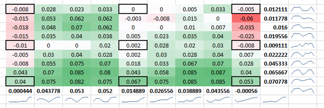
In looking at my bed mesh below, it would seem that in most cases that the bed anchoring points are stable (bolded cells) where as the area in between the anchor points tends to bow. Granted, I don't consider any of this mesh bad - and it has no visible effect on the parts printed - but as most, I'm always looking to push to the best achievable performance. This is what has me thinking to maybe loosen and then tighten the exterior points while the bed is heat stabilized.
Have either of you seen this before?
-
May I ask how this table was generated together with the nice colouring and stuff. Sure beats the standard spreadsheet display. Very easy to look over and see what is going on at a glance!
-
@Kolbi said in Height Map from my updated MarkForged style printer:
@fcwilt , @Phaedrux ,
Have either of you had any results, or ideas, on fastening the heated bed while it is cool / vice hot - or vice versa? I was wondering this the other day, expansion and such.As far as I know, the only way to do this that makes sense is a 'compliant mount'. The bed is only fastened rigidly at a single point. all other points allow movement in the x/y plane but not in Z. Typically it is a three point bed mount.
-
@jens55 It was pretty easy actually. I took the heightmap data points, copied them and pasted into a next text file and called it bed.csv. Then I opened this in Excel, used conditional formatting for the cell coloring, and then used sparklines for the end of each row. I played around with a few charting options and that data also showed the same displayed findings in this image. I'd say import it into excel and play around with it - kinda fun.
-
Very well done ... obviously the 'force' is with you!
My Excel 'foo' is nowhere near that level .... never mind the fact that I use open office in Linux for my spreadsheets.Edit: the bit that shows the graph of the particular row or column is insane - never seen that before !!!
-
-
Cooool ! Thanks!
-
@Kolbi said in Height Map from my updated MarkForged style printer:
@fcwilt , @Phaedrux ,
Have either of you had any results, or ideas, on fastening the heated bed while it is cool / vice hot - or vice versa? I was wondering this the other day, expansion and such.I recently switched to these silicone "standoffs" from the traditional springs I used to use.
They seem to work fine. The long term question is will they deform and change height.
As to hot/cold the M3 screws I use go through tapped holes in the heated bed and into M5 clearance holes in the bed support.
I believe that this should accommodate any expansion/contraction.
Frederick
-
@jens55 If OO doesn't show it correctly, let me know and I'll share it as a google doc once I get home.
-
@fcwilt @jens55, I have a mk52 style bed like the below pic. I am thinking that I could solidly mount the center, and then use semi-rigid standoffs for the perimeter fixation points.
Thinking about it, I could do a heat stabilized bedmesh, and then while keeping heat on, loosen and re-tighten the perimeters, and perform a second bedmesh - this should let me know if it is actually caused by bowing from heat expansion ....I think...
-
@jens55 Did the OO file work?
-
Yes it did except it did not display the graphs of the rows and column values which although neat, is not that important to me.
I have not had an opportunity to look at the underlying code yet. -
-
It doesn't give me permission to access.