Duet 2 Ethernet and SBC
-
@dc42 said in Duet 2 Ethernet and SBC:
@arhi said in Duet 2 Ethernet and SBC:
now question is how is simulation related to real stuff wrt sbc/duet communication
The simulation runs on the Duet, so the SBC to Duet traffic is much the same as for a real print, except for fewer status requests/responses because of the shorter duration.
Great, so I can assume this "link" between SBC and Duet2 is stable.
I intentionally put a DCDC close to the "link" and I have these long pins sticking out like antennas so "worse case scenario" and after the relativly long simulation I don't see any errors in the log. When I trim the pins and remove the DCDC from there it should be even better :).Awesome

btw, another question. How does the SBC+Duet work now? Similar to klipper where SBC is calculating paths and duet just executing stepping table or more like octoprint where SBC is streaming G-Code to the duet and the path calculation is executed on the Duet? (I know it's not identical to neither of those two but those are 2 extremes)
-
@arhi said in Duet 2 Ethernet and SBC:
btw, another question. How does the SBC+Duet work now? Similar to klipper where SBC is calculating paths and duet just executing stepping table or more like octoprint where SBC is streaming G-Code to the duet and the path calculation is executed on the Duet? (I know it's not identical to neither of those two but those are 2 extremes)
GCodes are pre-parsed on the SBC and certain operations (e.g. macro expansion) are done on the SBC. The motion calculation is done on the Duet.
-
@dc42 nice, so closer to octoprint than to klipper but unique ... /me like

-
I really like the Idea to use a SBC with the Duet 2! Really great work! Are there any plans to offer some official adapter(s) in future? (maybe in the DUET-Shop?) I'm ready to pay for such a nice solution like the adapter made by @arhi or @deadwood83.
-
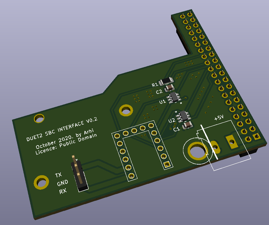
v0.2

- changed the shape of the board
- re-routed the comm tracks so that there's even less crosstalk
- cut the excess pcb from the side of the connector so that it does not interfere with those big heatsinks on SBC
- added 5V connector for SBC
Unfortunately it still does not clear panelDue and Probe connectors. I was thinking about changing the relation between duet and sbc connectors (to move the duet connector more towards other end of the sbc connector) but that would move the SBC more out of the allignment with the duet, already the SBC is 6mm in front of duet messing up the case design so looking at that I should move the connector the other way 6mm making access to those two ports even more problematic... so I'm leaving it as is. The way board is now shaped the cable from the probe port can come out but you either need to use the long pins for the duet connector or you need to desolder paneldue and probe connectors from duet and solder in 90 degree ones (this is what I will be doing myself)
-
JLCPCB fabrication data:
https://mega.nz/file/AvomlYgQ#H2On-xkR0LZO4Alfz3XwbGmhdHH57dhXkqwBkmfA9zgkicad project:
https://mega.nz/file/ovhVha7J#dEpw6RDbxD9zF51nwtblrdI7CGkv-v5sYsYhZ_GNx1slicence: public domain - a.k.a. "do what ya wish I don't care"
-
@arhi nice! what i learned with my STM32 LPC Pi adapters is that people would love atleast some gpio pins broken out of the PI and a DC in port

-
@PCR that's why there's a kicad file so anyone can add whatever one wants

5mm terminal block makes much more sense to me than DC barrel jack as this is not something that's going to be plugged/unplugged non stop, you screw in your wires and that's it... as for GPIO, SPI is already used by the DUET and that's usually what I expose from that 40pin connector .. i2c don't really work with wires so no point, 1wire is more/less dead so again no point... I exposed serial from the Duet, might be smart to expose serial from SBC too but .. if anyone wants it there are sources

I was actually thinking about doing a 4 layer board (difference in price is insignificant) with dual sbc connectors so I can connect opi too (opi has expansion connector rotated 180 degrees) as I believe opi would work for this purpose just as good as rpi or even better and I have ton of those ... but the v0 already works so I'm not that motivated ... I need to finish as soon as possible my rpi hat that will house all the sensors I need on the camera (I'm making 20 "devices" that will serve in my new house as security cameras, pid, smoke, temperature, humidity, air quality, voc.. sensors and access points so I need a hat to mount all the sensors on, still deciding if I want discrete spi adc or I wanna add some mcu with adc there)
-

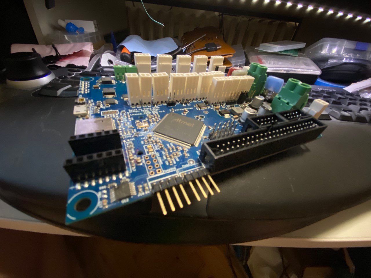
modified duet

I hate removing connectors from 4 layer boards but this was rather easy not a lot of thermal mass on the prc clone, obviously 1oz copper
 -
@arhi said in Duet 2 Ethernet and SBC:
I hate removing connectors from 4 layer boards but this was rather easy
That corner of the real deal is also the easiest to work with, not a lot of ground planes and heavy traces. But yeah, 1oz "helps"'D
-
This post is deleted! -
@bearer yup, I have some exp. desoldering from 4 layer 2oz and I had to preheat the board not to destroy the holes... this came out like it was a 2layer board
 ... anyhow, the adapter, as is, if one wanna use the probe and panel connectors operation like this is necesary
  .. and is def not for everyone (100000% kills your varanty
  )
)the "bottom add adapter" by @deadwood83 is probbly much better solution, I like this for me as I don't have any wires and it holds my sbc in place but not sure this approach is the best, I think his approach is much better.
-
@dc42 do you know if something like this is planed?
-
I've been having comms issues since installing one of @deadwood83's boards. It will connect fine in DWC, but every so often it will reset the controller. Looking at the log, it keeps getting bad checksum errors. I don't believe my wiring is to blame, but it could be. Any ideas?

The thick white cable + yellow wire comprise the connection to the pi. It is a bit of cat5 cable with connectors crimped on.

P.S.- Measuring the cable length, it's about 200mm. Maybe that could be the issue?
P.P.S- I do not have a duex. Just the duet.
-
More info:
- Letting the printer sit idle (heaters off, motors off) produces almost no errors.
- Letting the printer sit idle (heaters on, motors off) produces more errors.
- Running a simulation has no effect.
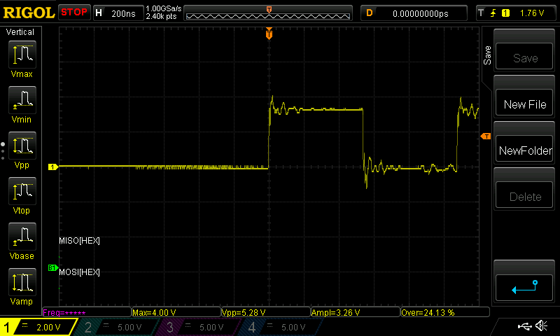
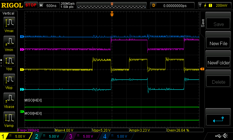
Scoping the SPI pins, the waves look to be well-formed. A little bit of jitter, but otherwise good.
Overall, it seems pretty random to me.
-
@SAtech I tested (with my "pcb-link" so no wires) so far only the simulation as I have no motors nor heaters attached to that duet board yet. If you run a long simulation, does it pass ok? you don't see any errors?
... === SBC interface === State: 0, failed transfers: 0 Last transfer: 20ms ago RX/TX seq numbers: 4497/4498 SPI underruns 0, overruns 0 Number of disconnects: 0 Buffer RX/TX: 0/0-0 -
@arhi Simulation seems to work. However, if I have the heaters on, it will give a few errors:
=== SBC interface ===
State: 0, failed transfers: 2
Last transfer: 11ms ago
RX/TX seq numbers: 27937/27939
SPI underruns 0, overruns 0
Number of disconnects: 0
Buffer RX/TX: 0/0-0
=== Duet Control Server ===
Duet Control Server v3.2.0-beta2
Code buffer space: 4096
Configured SPI speed: 4000000 Hz
Full transfers per second: 28.70
In the DCS log, it gives a few more than that, mostly bad checksum errors and disconnects.
When I try to print, that's when I get problems. When and how it errors out can vary. Sometimes it just stops, sometimes it causes erratic behavior (mis-probes the bed, halts in the middle of a move):=== SBC interface === State: 0, failed transfers: 3 Last transfer: 8ms ago RX/TX seq numbers: 34957/34958 SPI underruns 0, overruns 3 Number of disconnects: 0 Buffer RX/TX: 0/0-0 === Duet Control Server === Duet Control Server v3.2.0-beta2 Code buffer space: 4096 Configured SPI speed: 4000000 Hz Full transfers per second: 31.21In this instance, it got through the homing procedure and tried to probe the bed. It only probed one point, but three times, and then stopped.
DCS log:[warn] Bad header checksum (expected 0x2001, got 0xfb88) [warn] Bad header checksum (expected 0x2001, got 0xfb88) [warn] Bad header checksum (expected 0x2001, got 0xfb88) [warn] Note: RepRapFirmware didn't receive valid data either (code 0x00004000) [warn] Restarting transfer because the number of maximum retries has been exceeded [debug] Cancelled M83 ; use relative distances for extrusion [debug] Cancelled G92 E0 ; set extruder to zero [info] Aborted macro file bed.g [warn] File: ==> Cancelling unfinished starting code: G32 ; home axes, calibrate bed leadscrews, and load saved mesh heightmap [warn] Controller has been reset -
@SAtech I can't determine this from the image: do you have a direct ground connection between your RPi and your VIN PSU? I found that the ground pin on the Duet network header is not sufficient for this purpose.
-
@wilriker I do. I have two PSUs, one 24v and one 5v. All the grounds are connected in star topology, and the red/black connector on the pi is connected to 5v and ground.
-
It seems like it must be something software related, since I can't see any reason why it shouldn't work.
Just so I'm not crazy:

