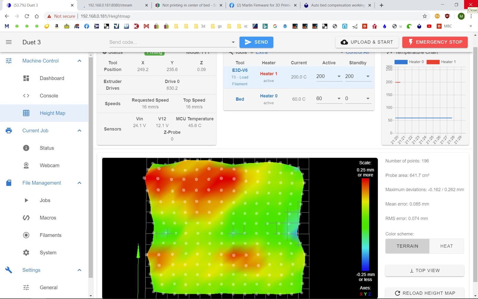
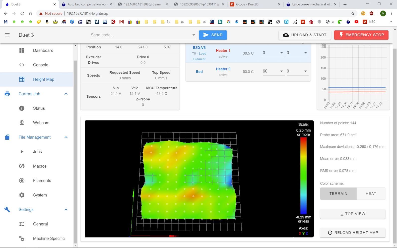
Auto bed compensation working just not very well
-
; bed.g
; called to perform automatic bed compensation via G32
;
; generated by RepRapFirmware Configuration Tool v2.1.8 on Wed Apr 29 2020 12:52:20 GMT-0600 (Mountain Daylight Time)

; Remember to include probe offsets in X and Y coordinates
G28                          ; home
M401                         ; deploy Z probe
G30 P0 X11 Y55 Z-99999         ; probe left front adjusting screw
G30 P1 X296 Y55 Z-99999       ; probe right front adjusting screw
G30 P2 X152 Y305 Z-99999 S3  ; probe middle rear adjusting screw and report adjustments needed
M402                         ; retract probe
; homeall.g ; called to home all axes ; ; generated by RepRapFirmware Configuration Tool v2.1.8 on Wed Apr 29 2020 12:52:20 GMT-0600 (Mountain Daylight Time) G91 ; relative positioning G1 H2 Z7 F6000 ; lower bed 7mm to ensure probe is above the Z probe trigger height G1 H1 X-310 Y-310 F2600 ; move quickly to X or Y endstop and stop there (first pass) G1 H1 X-310 ; home X axis G1 H1 Y-310 ; home Y axis G1 X5 Y5 F6000 ; go back a few mm X and Y G1 H1 X-310 F360 ; move slowly to X axis endstop once more (second pass) G1 H1 Y-310 F360 ; then move slowly to Y axis endstop G90 ; absolute positioning G1 X157 Y99 F2000 ; Move probe over to the center of the bed G30 ; lower probe, stop when probe triggered and set Z to trigger height, home Z by probing the bed ; Uncomment the following lines to lift Z after probing ;G91 ; relative positioning ;G1 Z5 F100 ; lift Z relative to current position ;G90 ; absolute positioningAnd since the new bed is thicker than the oem bed I'm preheating for 10 minutes before I start a print.
I'm now printing the same print without height comp. Will post when finished. -
@fcwilt Heightmap done yesterday with many probe points. Made me wonder about the quality of plate I received. A print with this height map was about the same as above.

-
; bed.g

G28                          ; home all
M561      ; clear any bed transform

; first run
G30 P0 X11 Y55 Z-99999         ; probe left front adjusting screw
G30 P1 X296 Y55 Z-99999       ; probe right front adjusting screw
G30 P2 X152 Y305 Z-99999 S3  ; probe middle rear adjusting screw and report adjustments needed

; second run
G30 P0 X11 Y55 Z-99999         ; probe left front adjusting screw
G30 P1 X296 Y55 Z-99999       ; probe right front adjusting screw
G30 P2 X152 Y305 Z-99999 S3  ; probe middle rear adjusting screw and report adjustments needed

G90                     ; absolute positioning
G1 X157 Y99 F2000       ; Move probe over to the center of the bed
G30                     ; lower probe, stop when probe triggered and set Z to trigger height, home Z by probing the bed
; z probe in config.g M558 P9 C"io4.in" H2 F60 R0.5 T6000 A10 S0.003 ; set Z probe to bltouch, set input to io 4 in, set dive height,set feed rate, set delay, set speeds G31 P25 X-4 Y59 Z3.20 ; set Z probe trigger Height, X and Y offset and trigger height M557 X10:290 Y60:300 P12:12 ; define mesh gridMake these changes in config.g and bed.g, reboot, and then run G32 and then G29. That should home the printer, adjust lead screws twice, reestablish Z0, and then do a more detailed mesh grid. 3x3 lacks the detail needed and the interpolation between the sparse points is causing adjustment that isn't actually there. Your grid needs a higher resolution.
The changes to the BLTouch will make it probe more accurately, but it will take longer.
-
@Phaedrux Sounds good, thanks
Also sorry , did not see slicer start script,
G90 ; absolute positioning T0 ; select tool M109 S200 ; wait for hotend temp M190 S60 ; wait for bed temp G28 ; home all axes G29 S1 ; load height map G1 X130.0 Y15 Z0.0 F2000 ; move tool G1 X40.0 E10 F1000 ; prime nozzle G92 E0 ; reset extruder G1 E-.65 ; retract 1 mm -
Hi,
You can also try forcing the probe to average a fixed set of readings.
For example in M558 an A value of 5 and a S value of -1 the firmware will take 5 readings at each point then average them.
While averaging takes longer I think you would get a truer picture of your bed.
Frederick
-
That is what @Phaedrux did in the above files I believe.
-
Not quite. I have it probe up to 10 times or until it gets two consecutive consistent readings, but it won't average them. Averaging them would only be desirable if the probe results themselves were always shifting around and never consistent. We'd only want to go down that route it it was probing all 10 times and never getting two results the same. In such a case you'd get an error saying unable to get consistent probe result and it would halt the routine.
-
I've made the changes, copied and pasted. G32 ended up@ .01 and .01. Did G29, took a long time Here is the new print.

Height map

-
have you tuned the extruder? The second half of a good first layer is the right flow rate for the height from the bed.
-
Now that you've got a good height map generated you can use G29 S1 to load a saved heightmap instead of redoing it every time.
Print something like this to test the heightmap over the entire surface of the bed rather than a full print of a small section. Much faster this way and will give a better idea if the mesh compensation is working.
-
@Phaedrux I have confirmed the amount extruded by measuring 100mm of filament and then extruding 100mm. Comes out to within about a mm.
-
@Phaedrux
New test print, Since this is a 3 layer print the pictures mask what the first layer looks like. As I watched the first layer being put down generally speaking the right side of the print was laid more closely to the bed than the left. On the left the layer lines were thinner and rounded under a magnifier. As the nozzle progressed from right to left I watched the Z stepper wheel lower the bed. This is what was happening with the previous print with the holes, started good on the right and got worse as it went left. Is there anything left that can be done?
And I do appreciate your time and effort to help me out on this!Front of printer is on the left, did it that way to avoid shadows, but got some anyway.
Want to mention that h.e. is a genuine e3dv6 and the Z lead screws are T8-2 instead of the more common T8-8. More turns per inch as opposed to T8's = better resolution I'm told.
Lower right

Lower left

Upper left

Upper right

-
Just to confirm, you have 3 motors for your 3 bed lead screws for the auto leveling, right?
Are you sure the positions are correct?
Is there much deviation after each iteration of G32?
-
Just 2 lead screws and 1 stepper , I use G32 to adjust the 3 spring loaded bed leveling screws. Very little variation between iterations, day to day = some change, .03 +or-.
-
What is your nozzle width? What slicer are you using? What line width and layer height are you using for the first layer?
-
The only other thing I noticed is the trigger height is a bit high.
G31 P25 X-4 Y59 Z3.20When the BLTouch is mounted correctly the base of the probe should be ~8mm above the nozzle tip which leads to a trigger height of ~2mm, when you get too far away from that the BLtouch can be a bit off sometimes. It has a sweet spot.
-
Nozzle .4mm, S3d V4.12, flh 90%, flw 100%
Bltouch base is now 8.25mm above bed (mechanical limitation prevents 8mm) with nozzle touching bed, new trigger height = 1.40mm.