Mesh Compensation - big problems - something is wrong there
-
Hi,
I'm struggeling with my issue since weeks. I posted it here erlier, send my configs and till today nobody could found any reason for it.I entered a Facebook group (Duet3d Unofficial) and found out, that there are many more people with the same problem: mesh compensation didn't do it's job.
After many discussions here and there I made some sequences to check if results are repeatable - and yes - it is. So my conclusion is, that there are somewhere deep in the RAM are old values stored which leads to wrong bed calculations.
As I had independent z configured as first (with RRF2.0x) then went over to non-independent, went back to independent, go on to RRF3.0.xRCx. Having made a full earase and reinstalled the FW again - the issue is still there.
So I asked again @dc42: do you have any idea, what could be the reason for, that the calculated bed didn't match manually measurements at all?
I measured manually the same points which G29 did - and allways G29 delivers other results.
The next: I power up, run
M561
G29 S2
G32
and got a correction of -0.065/0.059, then I run G32 again and got (as expected) -0.004/-0.002 (where it should be 0.0/0.0 - but errors in that range are ok).
After this:
G29
49 points probed, min error -0.090, max error 0.046, mean -0.019, deviation 0.035
which should be ok.
Then after this I run G32 again (and it doesn't matter if I run again M561, G29 before ore not): -0.043/-0.026
and this is repeatable as often as I like.
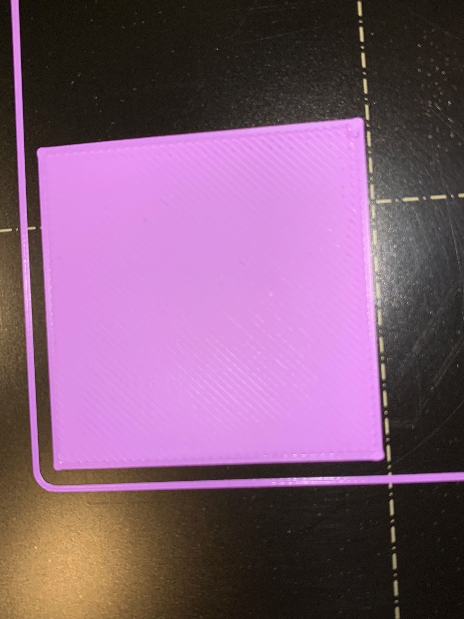
When printing a test pattern allways on the left side the nozzle is to far from the bed, in the middle is ok and on the right side it is too close to the bed, and again - it does not depend from z-motor configuration if it is independent or not. Also I changed all steppers to exclude something here and the BLTouch. Only the Wifi-Board I didn't change till now.As readers shoudln't search for long, here are all machine details (but again - in the FB group are many user with different setups and the SAME problem!). I also add some pictures for the problems below.
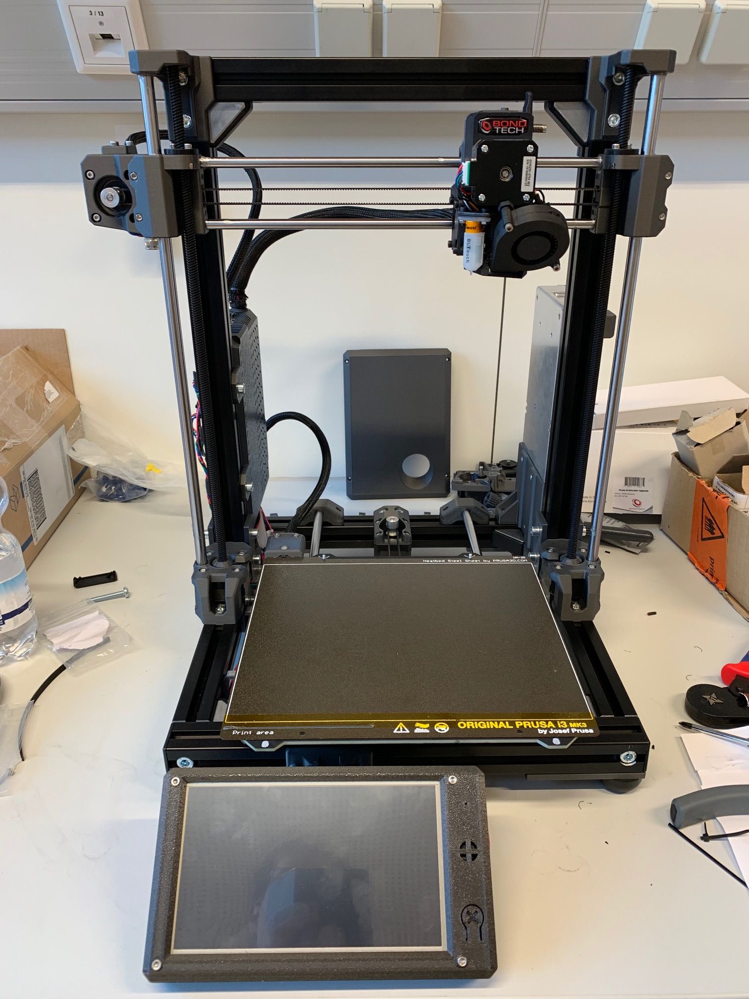
Printer is a Prusa-Like setup, Duet2 1.04 Wifi-Board, actual RRF3.01RC3
x,y steppers: Nema17/48mm 1,8° / 200 steps / 2A,
z-steppers Nema17 35mm 1,8° /200 steps / 1A with TR8x8 leadscrew
Mosquito/BMG Hotend with stepper: 1.8°/200 steps / geared 1:3
Magnetic MK52 Board@24 V, Meanwell 320W PSU, original BLTouch v3.1
if I forgot details, please ask for.config.g
G90                                                       ; send absolute coordinates...
M83                                                       ; ...but relative extruder moves
M550 P"Mjolnir"                                           ; set printer name

; Network
M552 S1                                                   ; enable network
M586 P0 S1                                                ; enable HTTP
M586 P1 S1                                                ; enable FTP
M586 P2 S0                                                ; disable Telnet

; Drives
M569 P0 S0                                      		  ; physical drive 0 goes backwards - x-axis
M569 P1 S0                                       		  ; physical drive 1 goes backwards - y-axis
M569 P2 S0                                       		  ; physical drive 2 goes backwards - z - left
M569 P3 S1                                       		  ; physical drive 3 goes forwards  - Extruder
M569 P4 S0												  ; physical drive 4 goes backwards - r - right
M584 X0 Y1 Z2:4 E3                                		  ; set drive mapping
M671 X-36.5:293.5 Y0:0 S1.0 		   	   		 		  ; leadscrews at left (connected to Z) and right (connected to E1) of X axis
M350 X16 Y16 E16 Z16 I1                                   ; configure microstepping with interpolation

M92 X100.00 Y100.00 Z400.00 E415.00                       ; set steps per mm
M566 X620.00 Y620.00 Z20.00 E300.00                       ; set maximum instantaneous speed changes (mm/min)
M203 X12000.00 Y12000.00 Z360.00 E1800.00                 ; set maximum speeds (mm/min)
M201 X1000.00 Y1000.00 Z200.00 E2000.00                   ; set accelerations (mm/s^2)
M906 X1600 Y1600 Z850 E800 I30                              ; set motor currents (mA) and motor idle factor in per cent
M84 S30                                                   ; Set idle timeout

; Axis Limits
M208 X-1 Y-5 Z0 S1                                        ; set axis minima
M208 X254 Y210 Z310 S0                                    ; set axis maxima

; Endstops
M574 X1 S3                                                ; configure sensorless endstop for low end on X
M574 Y2 S3                                                ; configure sensorless endstop for high end on Y
M574 Z1 S2                                                ; configure Z-probe endstop for low end on Z
M591 P2 C"e1_stop" S1									  ; configure extruder endtstop (filament sensor)

; Stallgaurd Sensitivy
M915 X S2 F0 H200 R0		        	 				  ; Set X axis Sensitivity
M915 Y S1 F0 H200 R0		          	 				  ; Set y axis Sensitivity

; Z-Probe
M950 S3 C"exp.heater3"                                    ; create servo pin 0 for BLTouch
M558 P9 C"^zprobe.in" H5 R0.25 S0.003 F120 T3000 A10 B1   ; set Z probe type to bltouch and the dive height + speeds
G31 P125 X-22.6 Y-34.7 Z2.40                              ; set Z probe trigger value, offset and trigger height
M557 X5:230 Y10:175 P7:7                                  ; define mesh grid

; Heaters
M308 S0 P"bedtemp" Y"thermistor" T100000 B4138 A"Bed"     ; configure sensor 0 as thermistor on pin bedtemp
M950 H0 C"bedheat" T0                                     ; create bed heater output on bedheat and map it to sensor 0
M143 H0 S110                                              ; set temperature limit for heater 0 to 110C
M307 H0 B0 S1.00                                          ; disable bang-bang mode for the bed heater and set PWM limit
M140 H0                                                   ; map heated bed to heater 0
M308 S1 P"e0temp" Y"thermistor" T500000 B4681 C1.143895e-7 A"Nozzle" ; configure sensor 1 as thermistor on pin e0temp
M950 H1 C"e0heat" T1                                      ; create nozzle heater output on e0heat and map it to sensor 1
M143 H1 S280                                              ; set temperature limit for heater 1 to 280C
M307 H1 B0 S1.00                                          ; disable bang-bang mode for heater  and set PWM limit
M308 S4 P"mcu-temp" Y"mcu-temp" A"MCU"					  ; set virtual heater for MCU
M308 S5 P"drivers" Y"drivers" A"Driver"				      ; set virtual heater for stepper drivers

; Fans
M950 F1 C"fan1" Q500                                      ; create fan 1 on pin fan0 and set its frequency
M106 P1 S1 H1 T45                                         ; set fan 1 value. Thermostatic control is turned on
M950 F0 C"fan0" Q500                                      ; create fan 0 on pin fan1 and set its frequency
M106 P0 S0 H-1                                            ; set fan 0 value. Thermostatic control is turned off

; Tools
M563 P0 D0 H1 F0                                          ; define tool 0
G10 P0 X0 Y0 Z0                                           ; set tool 0 axis offsets
G10 P0 R0 S0                                              ; set initial tool 0 active and standby temperatures to 0C
M302 S190 R190

; Custom settings are not defined
M501 													  ; use config-override (for Thermistor Parameters)
homex.g
G91                ; relative positioning
G1 H1 Z5 F180
G1 H1 X5 F1000     ; move slowly away
M913 X20           ; lower motor current to 20% for senserless homing
G1 H1 X-260 F2000  ; move quickly to X axis endstop and stop there (first pass)
G1 X10 F1000       ; go slowly back a few mm
G1 H1 X-260 F2000  ; move to X axis endstop once more (second pass)
M913 X100          ; Rise motor current to 100% again after sensorless homing
G90                ; absolute positioning
G1 X15 F1000	   ; go to X=15
homey.g
G91                ; relative positioning
G1 H1 Y-5 F1000    ; move slowly away
M913 Y30           ; lower motor current to 30% for senserless homing
G1 H1 Y230 F2000   ; move quickly to Y axis endstop and stop there (first pass)
G1 Y-10 F1000      ; go back a few mm
G1 H1 Y230 F2000   ; move slowly to Y axis endstop once more (second pass)
M913 Y100          ; Rise motor current to 100% again after sensorless homing
G1 Y-10 F1000      ; go back a few mm
G90                ; absolute positioning
homez.g
G91                   ; relative positioning
G90                   ; absolute positioning
G1 X147.6 Y139.7 F3600    ; Move probe to middle of bed - first probing point, regarding Z-probe offsets
G30                   ; home Z by probing the bed
G91                   ; relative positioning
G90                   ; absolute positioning
homeall.g
M98 P"homex.g"           ; Call "homex.g"
M98 P"homey.g"           ; Call "homey.g"
M98 P"homez.g"           ; Call "homez.g"
bed.g
M561 									; Clear any bed transform
G29 S2									; Clear bed height map
G30 P0 X10 Y105 Z-99999					; probe near left leadscrew, half way along Y axis
G30 P1 X230 Y105 Z-99999 S2 			; probe near right leadscrew and calibrate 2 motors
G90 									; Absolute Positioning
G1 X125 Y105 Z25 F5000.0 		        ; go to the middle of the bed
My normal start sequence:
M561
G29 S2
G28
G32
G32
G29 (only at the moment - my aim is to get a reliable config, that I just to have load a mesh...)
start print
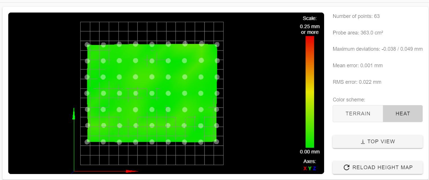
As described here are the pictures:
left

right where you can clearly see, that the nozzle is way too deep:

mesh (which was measured for the prints in the pictures):

printer:

-
@tom_Nbg said in Mesh Compensation - big problems - something is wrong there:
@dc42: do you have any idea, what could be the reason for, that the calculated bed didn't match manually measurements at all?
Thanks for providing such detailed information. What seems to be happening is that the X tilt reported by the BLTouch doesn't match the actual X tilt. This implies that the relative heights of the BLTouch trigger point and the nozzle are not constant across the X axis.
I think this is inevitable with your printer to a small extent. Some observations:
-
When you home Z using G30 at approximately bed centre, then run G32 to level the two Z motors, you get corrections averaging about -0.06mm. IOW, it's behaving as though the edges of the bed are about 0.06mm lower than the centre. So either the bed is bowed (which is quite likely if you are probing with the bed heated), or the print head sags when at the centre of the X axis (perhaps because the X rods are too thin to properly support the weight of the print head without a small amount of bending).
-
Your BLTouch is offset from the nozzle by 22mm in the X direction.
The fact that the distance between the nozzle and the bed describes an arc when moving in the X direction means that the relative heights of the nozzle and BLTouch vary depending on whether you are at the left hand end, middle, or right hand end of the X axis.
That said, I would expect the size of this effect to be small, well below the 0.06mm difference in nozzle height between bed centre and edges.
So I suspect that you have a small amount of relative twist between the two X rods, such that the print head assembly rotates slightly about the X axis as it moves along it. Then the Y offset between the nozzle and BLTouch will come into play, causing the relative heights of the nozzle and BLTouch to vary with X. Have you tried holding a spirit level vertically so that it touches both X rods, at each end of the X axis? Given your 35mm BLTouch Y offset, a rotation of just 0.2 degrees will cause the BLTouch trigger height to change by 0.1mm relative to the nozzle, enough to explain the effect you observe.
To check this, measure the trigger height of the BLTouch (see https://duet3d.dozuki.com/Wiki/Test_and_calibrate_the_Z_probe#Section_Calibrate_the_Z_probe_trigger_height) at varying positions along the X axis. I think you will find that it varies significantly.
HTH David
-
-
Thank you for your reply and your thoughts
I understand what you mean - and I never thought on this (allways my thought was, if there is a mechanical issue when moving BLTouch should detect it also... - but this enlighten me to this point).I'll have a look for and print another holder to mount the BLTouch on the right side - closer to the nozzle and with zero y-offset (there is a place at the BMG for the PINDA Probe) - so then the effect should get smaller or vanish.
I'll report.
Thank you again -
the bed may bow .... however - your initial Mesh Grid probing had it nearly perfect at one point - not sure if that near perfect mesh grid probe routine early on was HOT or ambient - pretty sure you mentioned it was HOT.
Im going to go with a combo of all 3 of the items mentioned by DC42 - Heat causing the pcb to bow slightly .... some minor twist [ perhaps a very small amount ] and MOST of this imho is the 8mm rods sagging in the center of the X travel. Now you understand why I wanted linear rails or a 10-12mm smooth rod setup for X. Ive opted for my new printer - MGN12 - like Stefan Webers.
You resolved the shortcomings in the Y axis so well - now its exacerbated the flaws in the X

Just my humble thoughts ... the modding never ends
-
Thank you for the great reply - im having similar issues and have been for ages. I had been chalking it up to the BuildTac Magbed stick on sheet as being the culprit - but I suspect now it is - for me - a combo of all those 3 issues you mentioned above + the Magbed.
I need a bridgeport Knee mill some MIC6
