Useing JMC Servo Motors for X and Y Axis movement
-
Hi.
I am in the process of building a industrial 3D Printer and planned to use JMC Servos for the movement of the X and Y Axis.
The Printer is build with CoreXY. In my configuration i have a Duet Ethernet with the Duet5X Extension and connected the Servo motors to the LCD Con Pins useing the Duet Breakout Expansion Board for Level shifting.
This configuration works. I can move all the axis with "normal" steppers and also the servo driven X and Y axis. But when printing i have issues of loosing steps in X and Y.
I am quite sertain, that this is not a mechanical issue here. Instead i think either the Servo Controller is "forgetting" its position (which shouldn'nt be possible.. i mean thats the point of useing servos, right?) , the communication is bad or maybe the Duet has a software bug when useing external drivers.
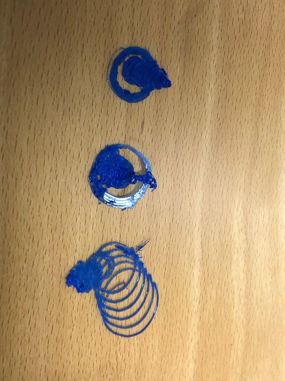
Here is what the prints look like:The printed object is a little cylinder that is about 8mm in diameter and should be a couple mm high. The outer ring resembles skirt.
I tried different accelerations to see, if maybe the Servos couldn't keep up.
The uppermost one is printed with accelerations set to 3000mm/s2,
The middleone with 2000mm/s2
the lower one with 200mm/s2.
So as you can see it gets worse with lower accelerations.
 !
!For me it looked like it lost position each time the XY Movement stopped
, for example after one ring of Skirt was finished, the printhead stops and moves a bit for the next ring, also when the layer is changed, it also shifts quite a bit.Also you can clearly see, that the skirt is not round, which is the fault of the servos PID control i guess.
At this point i am a bit confused, how i should proceed.
Has somebody used the LCD_Con pins to drive external steppers, and did it work properly?Do you have ideas, how i should proceed, the find out, which part of the machine is responsible for the lost steps?
Thanks a lot
Cheers,
Alex -
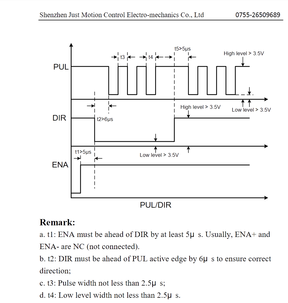
With external drivers it's critical to be aware of minimum pulse time requirements for drivers (see
M569command).Most external drivers will require longer step pulses than the on-board drivers, this could be why you are losing steps.
Here is an example from a datasheet from JMC showing pulse timings which you would have to guarantee with the M569 command:

-
Thanks, for the input! I will have a closer look tomorrow morning.
Cheers,
Alex -
Dear @nhof, thanks for pointing me into the right direktion.
Indeed M569 did the trick.
These settings work fine for me:M569 P10 S0 R1 T4:4:8:7
M569 P11 S1 R1 T4:4:8:7The motors are absolutely wicked.
I run them on 24V and on the highest resolution settings- 40.000steps/rev. , which results in 474.8 steps/mm for X and Y. I use HTD3M Belts and 37Tooth Pulleys.Cheers,
Alex -
HTD belts aren't really designed for positional accuracy, they are designed for high-torque, usually uni-directional loads, like a car fan belt. From the SDP/SI "Handbook of Timing Belts, Pulleys, Chains and Sprockets" page T-5: "The HTD design requires substantial belt tooth to pulley groove clearance (backlash) to perform". And backlash is even worse on smaller pulleys. The backlash is needed to get the belt tooth into the pulley groove; without it, the tooth will 'twang' into, and out of, the pulley, causing a vibration in the belt. The design of GT2 pulleys and belts improves this, and would be a better choice for reduced backlash.
See this discussion for more HTD details: https://www.thingiverse.com/thing:16627/comments/#comment-2473684
Ian