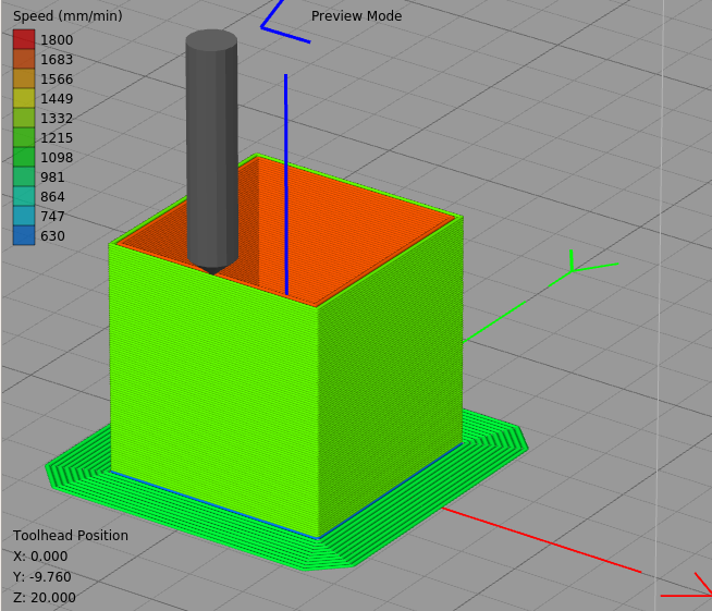
Calibration cube corners.
-
@obeliks My "config.g":
; Configuration file for Duet WiFi (firmware version 1.21)
; executed by the firmware on start-up
;
; generated by RepRapFirmware Configuration Tool on Mon Aug 06 2018 00:13:45 GMT+0100 (IST); General preferences
G90 ; Send absolute coordinates...
M83 ; ...but relative extruder moves
M555 P1 ; Set firmware compatibility to look like RepRapFirmare;*** The homed height is deliberately set too high in the following - you will adjust it during calibration.
M665 R105.6 L267 B90 H212 ; Set delta radius, diagonal rod length, printable radius and homed height
M666 X0 Y0 Z0 ; Put your endstop adjustments here, or let auto calibration find them; Network
M550 PMy printer ; Set machine name
M552 S1 ; Enable network
;*** Access point is configured manually via M587
M586 P0 S1 ; Enable HTTP
M586 P1 S0 ; Disable FTP
M586 P2 S0 ; Disable Telnet; Drives
M569 P0 S0 ; Drive 0 goes forwards
M569 P1 S0 ; Drive 1 goes forwards
M569 P2 S0 ; Drive 2 goes forwards
M569 P3 S1 ; Drive 3 goes forwards
M350 X16 Y16 Z16 E16 I1 ; Configure microstepping with interpolation
M92 X80 Y80 Z80 E407 ; Set steps per mm
M566 X1200 Y1200 Z1000 E1000 ; Set maximum instantaneous speed changes (mm/min)
M203 X12000 Y12000 Z12000 E1200 ; Set maximum speeds (mm/min)
M201 X1000 Y1000 Z1000 E1000 ; Set accelerations (mm/s^2)
M906 X1000 Y1000 Z1000 E800 I30 ; Set motor currents (mA) and motor idle factor in per cent
M84 S30 ; Set idle timeout; Axis Limits
M208 Z0 S1 ; Set minimum Z; Endstops
M574 X2 Y2 Z2 S1 ; Set active high endstops; Z-Probe
M558 P5 R0.4 H5 F1200 T6000 ; Set Z probe type to effector and the dive height + speeds
G31 P100 X0 Y0 Z-0.1 ; Set Z probe trigger value, offset and trigger height
M557 R90 S20 ; Define mesh grid; Heaters
M307 H0 B0 S1.00 ; Disable bang-bang mode for the bed heater and set PWM limit
M305 P0 T100000 B4138 C0 R4700 ; Set thermistor + ADC parameters for heater 0
M143 H0 S120 ; Set temperature limit for heater 0 to 120C
M305 P1 T100000 B4138 C0 R4700 ; Set thermistor + ADC parameters for heater 1
M143 H1 S280 ; Set temperature limit for heater 1 to 280C; Fans
M106 P0 S0.3 I0 F500 H-1 ; Set fan 0 value, PWM signal inversion and frequency. Thermostatic control is turned off
M106 P1 S1 I0 F500 H1 T45 ; Set fan 1 value, PWM signal inversion and frequency. Thermostatic control is turned on
M106 P2 S1 I0 F500 H1 T45 ; Set fan 2 value, PWM signal inversion and frequency. Thermostatic control is turned on; Tools
M563 P1 D0 H1 ; Define tool 1
G10 P1 X0 Y0 Z0 ; Set tool 1 axis offsets
G10 P1 R0 S0 ; Set initial tool 1 active and standby temperatures to 0C; Automatic saving after power loss is not enabled
; Custom settings are not configured
; Miscellaneous
T1 ; Select first tool
M501 ; new commands override the ones earlier in your config.g -
Can you take a photo from the side of the print? Still looks like a mechanical issue to me, but need to see more angles I think.
-
-
Side like looking at the perimeters, not top, thanks
-
I’m nearing my wit’s end (usually not a long journey), and would really appreciate some help. I print with a FlashForge Creator Pro, using a glass planers for a bed, and ABS juice for adhesion. I’ve been having problems with some prints. I’ve been through the print quality guides on duet3d but haven’t yet found the magic formula. I’m printing a simple 10X20X20mm cube that exhibits the issues I’m having. The .STL came with the printer. I print with Hatchbox filament.
-
-
-
@rcarlyle Sorry, fixed.

-
@johhnyalter, the cube printed 5C lower appears to me to have better corners. Can you confirm that? If so then it confirms my view that excessive speed and/or temperature is the problem. So I suggest you reduce temperature, or add a little fan cooling, or reduce XY acceleration and/or jerk.
-
The fact that the base starts at the correct shape and then it deforms increasing amounts near the heatbed, then gets a little better as it gets higher... that really suggests that it's an issue with the plastic not cooling fast enough. Proximity to the heatbed = more heat. Small print = not much time for heat to conduct away from the top layer. Corners = slower nozzle motion for more heat radiation into the print.
Do you have an insulated hot block?
Do you have ANY kind of airflow, even gentle airflow, in the printer? I find ABS quality benefits enormously from very gentle airflow.
What happens when you print something 4x bigger (ie more time for plastic to cool before the nozzle approaches again)? -
It IS kind of unusual geometry for a corner overheating/undercooling issue, though. Would really like to see video of the box printing.
-
ABS suffers from slow printing, too much heat is transferred and you end up sagging the layers under the layer you are printing, try bringing the speed up to 50mm/sec. A small amount of air flow will sharpen up the edges but will also make the part super brittle unless you can keep the air temp above 60*C.
You also are clearly over extruding which will be exacerbate the layer issues
-
Thanks for respond guys
-
First of all, many thanks for your help. Your tips helped me find more or less accurate settings.
But I think I found the "root" of my problem.
Just look at the result of alternate printing with exactly the same settings.


Do you think this is a problem with the heater?
Regards. -
So one corner is bad at all heights, the others are poor close to the bed but OK at greater heights. I don't know about the corner that is always poor, but I think the others are suffering from too much heat rising from the bed.
What bed temperature are you using? Do you have a minimum layer time configured in the slicer?
-
-
Allowing speed reductions down to 70% doesn't allow for much slowdown at all. I suggest 10% to 20%.
-
Also another thing to try is printing a significantly bigger cube.
The one corner that is always bad is probably where each layer starts and finishes so once the other corners are good you can work on tuning retract length, speed and possibly pressure advance to make that better.


 you're going in the wrong direction! like this:

